Report configuration
In this article we will analyze the windows that allow the user to configure the report by modifying the main report’s properties such as the layout, the language, the units for the physical quantities, and the sections to be printed.
The most useful window for modifying the report properties is the “Item Report” window, accessible from the “Item Report” button under the “Item” tab of the ribbon bar:
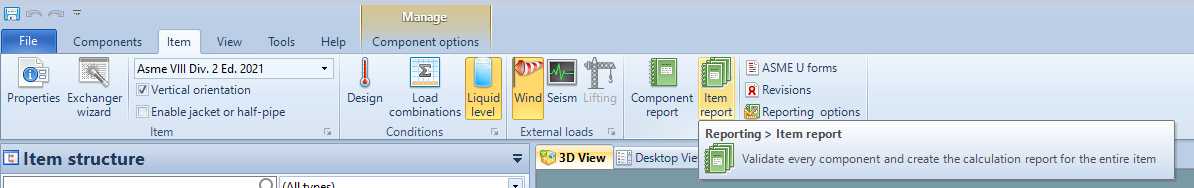
"Item Report" button
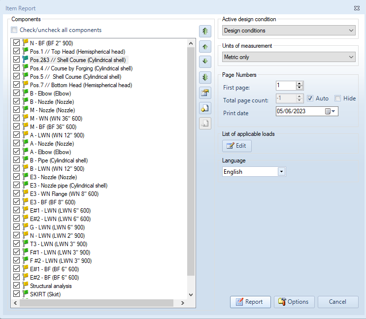
"Item Report" window
Components
At the left hand side of the window the user can select the components to include in the final calculation report.
The user can move report sections upwards or downwards using the up and down arrows:


Up and down arrows for moving report sections
The user can also move a report section all the way up or down using the up and down double arrows:


Up and down double arrows for moving report sections all the way up or down
For looking at a summary of the validation details for a given component the user can click the button below:

"Validation details" button
Empty pages can be used to leave a gap in the pages numbering of the calculation report for the insertion of a portion of the final report made with an external program. The table of contents will also display the page number where such external pages will appear. A section containing empty pages can be added by clicking on the button below:

"Add empty pages" button
The user can specify the section title and the number of empty pages to insert:
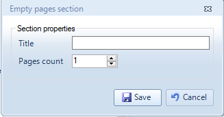
"Empty pages section" window
The user can use this button to remove the section with empty pages:

"Remove empty pages" button
Active design condition
On the right hand side of the “Item Report” window, the user can specify the active design condition for which he/she wants to perform the calculation and print the calculation report (this is useful when multiple design conditions are in use):
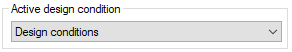
Active design condition
Units of measurement
The user can also choose to print the calculation report in metric units, customary units, or both:
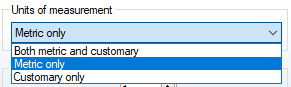
Units of measurement
Page Numbers
The user can choose to start the numbering of the pages from a number higher than 1 by modifying the number of the first page of the calculation report:
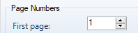
First page
By disabling the “Auto” option, the number of the total pages, that appears on the bottom of every page, can be modified:

Total page count
The user can modify the print date that appears on the report:

Print date
List of applicable loads
The user can customize the "List of applicable loads" section of the calculation report by clicking on the "List of applicable loads" button:
"List of applicable loads" button
The list of applicable loads is particularly relevant in ASME calculations, e.g. according to ASME VIII Division 1 UG-22. This option should be used in combination with the "Print list of applicable loads" available in the report options, explained below.
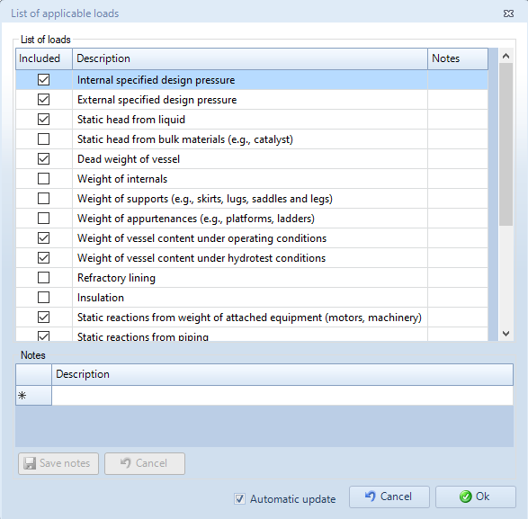
"List of applicable loads" window
Language
The user can choose the report language from the available languages (the available languages depend on the calculation code):
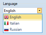
Language
Options
The user can click on the "Options" button, to further customize the calculation report:

"Options" button
The same report options can be customized from the "Reporting" section of the "Options" window, accessible from the "Options" button in the "Tools" tab of the ribbon menu:
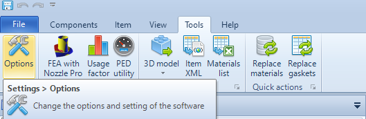
"Options" button in the "Tools" tab
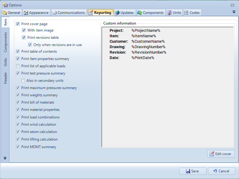
"Reporting" section of the "Options" window
In the "Item Report Options" window accessible form the "Options" button of the "Item Report" window, the user can choose whether to use the software default settings defined in the "Reporting" section of the "Options" window or to personalize them.
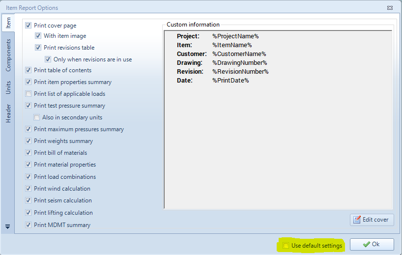
"Item Report Options" window
Let's now analyze the properties that can be customized from the "Item Report Options" window. For most of the properties the meaning is straight forward, thus we will analyze only the properties for which an explanation is necessary.
Item
Print item properties summary
Prints a summary table of the main properties set at item level from the window "Item properties"
Print list of applicable loads
Prints a summary table of the loads considered and not considered for the item design
Print maximum pressures summary
Prints a summary table of the maximum allowable pressure values internally and externally for each component
Print weights summary
Prints a summary table of the weighs considering also the load combination coefficients
Print material properties
Prints for each material a summary table of the main material properties
Print load combinations
Prints a summary table of the load combination's coefficients
Edit cover
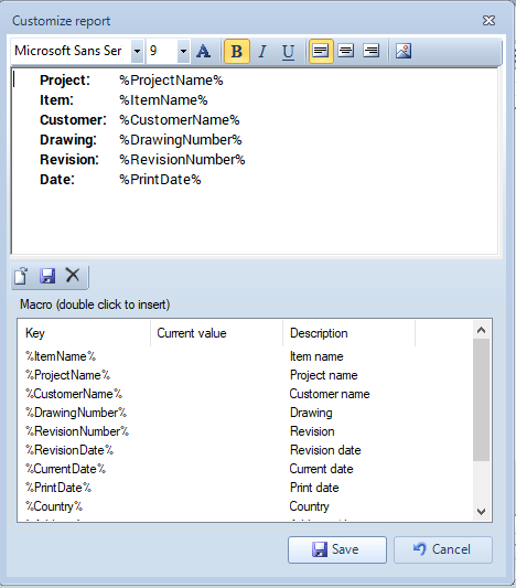
The window that allows the user to edit the report cover
The window that allows the user to edit the report cover is made of two main areas, one above and the other below. In the area below we find a list of keys, that allows the user to insert in the report various properties like the item name, the project name, etc. To do this, we shall click two times over the key that we want to insert and the key will be inserted in the area above. In the image above the current value of the various properties (item name, project name, etc) is empty since we are looking at the default report properties, if instead we looked at the properties of a single report the various properties would have as a current value the corresponding text for the given item. In the area above we can modify the text that will appear in the report. For example, if we want to add also the address of the item in the cover of the report and the text "PRJ" before the project name, we can do this like shown in the image below:
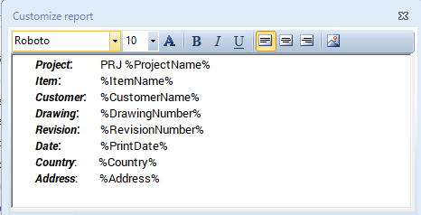
Example of a modified report cover
Components
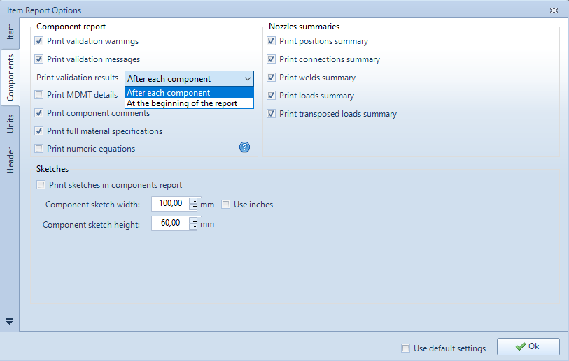
Report options present in the "Components" tab
Component report
Print validation results "After each component" or "At the beginning of the report"
If "After each component" is selected, the validation results (errors, warnings and messages) will be printed after the component they belong to, if "At the beginning of the report" is selected, the validation results (errors, warnings and messages) of all the components will be printed in a separate section at the beginning of the report.
Print MDMT details
Only for ASME calculation codes: prints a section related to the Minimum Design Metal Temperature
Print component comments
For each component prints the comments made at the "Reporting" section of the component's design window
Print numeric equations
Prints the equations substituting the symbols of the variables with their numerical values
Nozzles summaries
Print positions summary
Prints a summary table of the nozzles positions relatively to the components in which these nozzles are inserted
Print connections summary
Prints a summary table of the connections between nozzles and flanges
Print welds summary
Pirnts a summary table of the welding data for the nozzles
Print loads summary
Prints a summary table of the loads applied at the nozzles
Print transposed loads summary
Prints a section that how the nozzle loads are transferred at the base
Units
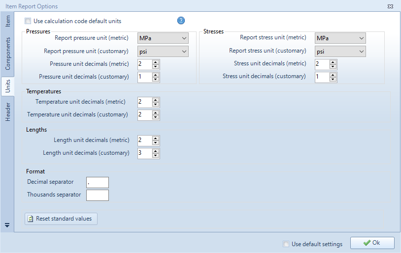
Report options present in the "Units" tab
The properties present in this section allow the user to choose the metric and customary units of the various physical and mechanical quantities and the number of decimals for these units.
The user can also choose to use the calculation code default units, leaving the choice of the units to be automatically done by the software.
Header
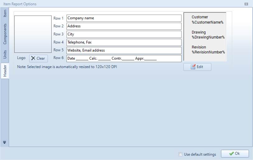
Report options present in the "Header" tab
The properties present in this section allow the user to edit the header of the report.
Logo
By clicking in the rectangle on the left upper part of the window the user can choose an image to put as a logo in the report header.
Header central part
The header central part contains 6 rows that can be compiled by the user with the desired text
Header right part
In the right part of the header the user can add the various properties of the item and of the project using the keys mechanism described in the "Edit cover" section. If the user clicks at the "Edit" button a window appears that allows the user to modify the text.

The window that allows us to modify the right part of the header
Report
To produce the final calculation report, the user shall click the "Report" button:

"Report" button