How to create an additional component with the "Desktop View"
Although the NextGen 3D modeler offers in most cases the flexibility needed to calculate the entire equipment, in certain cases it may be useful to go beyond its geometric constraints and design one or more components, or the entire item, using a design mode that allows you to calculate one component at a time, keeping the relationships between them to the bare minimum.
In NextGen this mode or view is called "Desktop View", or modeling of additional components.
The concept of an additional component is to be seen in relation to the 3D device; this working mode was born as an extension of it, so the components created here are additional to the 3D model. However, nothing prevents you from designing all the components with this mode.
Activate the Desktop View
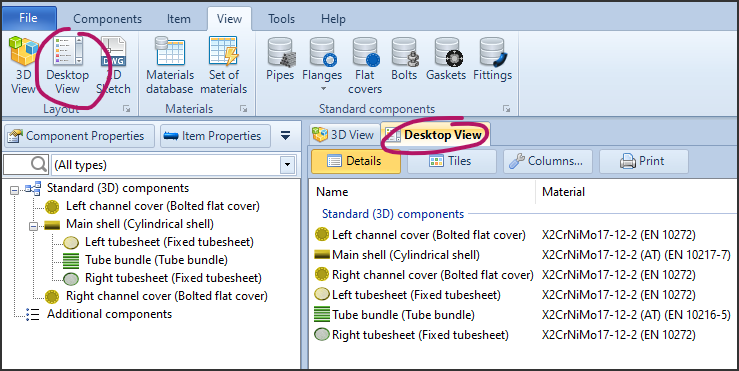
- In the ribbon, choose
View > Desktop View - Alternatively, use the tab next to
3D Viewabove the 3D workspace
Create a new component
When Desktop View is active, the components displayed with the active icon and therefore insertable in the current calculation will no longer be contextual to the currently selected component, but will all be activated.
Contextuality, or the need to select a component to connect another connected to it, will remain only for components that have a close "parent-child" relationship, such as nozzles connected to shells: in this case, given the strong dependency, it is not possible to design a nozzle without associating it with a parent component.
Once a component is created, it will be listed in a separate group called Additional components, as opposed to the components designed in the 3D view listed under Standard (3D) components
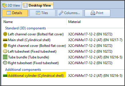
Creating a component by copying another from the 3D view
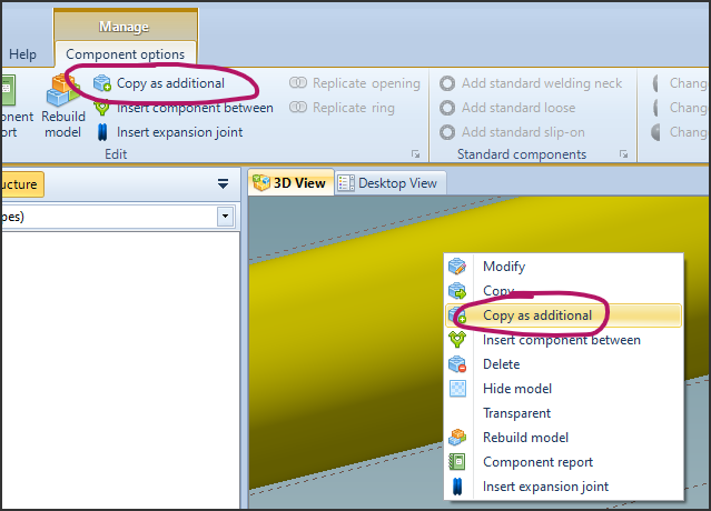
Another way to create an additional component is to duplicate an existing component in the 3D view. This can be useful for performing a study on that component without touching the original.
Clicking on the component to be copied in the 3D view will bring up the context menu, from which you can choose "Copy as additional component". The same function is available in the ribbon.
Additional features available in the Desktop View
Since this view shows a list of components, it can be used to have an overview of the properties of the components, even without necessarily adding additional ones.

The columns of this view are customizable and there is a button that allows you to print the current list.
A suggestion for use is to check the materials used, or to check the correct setting of the welding efficiencies on the various components.
Peculiarities of additional components
Additional properties
Some components require properties related to adjacent components to perform the calculation. Since additional components are disconnected from each other, these properties must be specified manually.
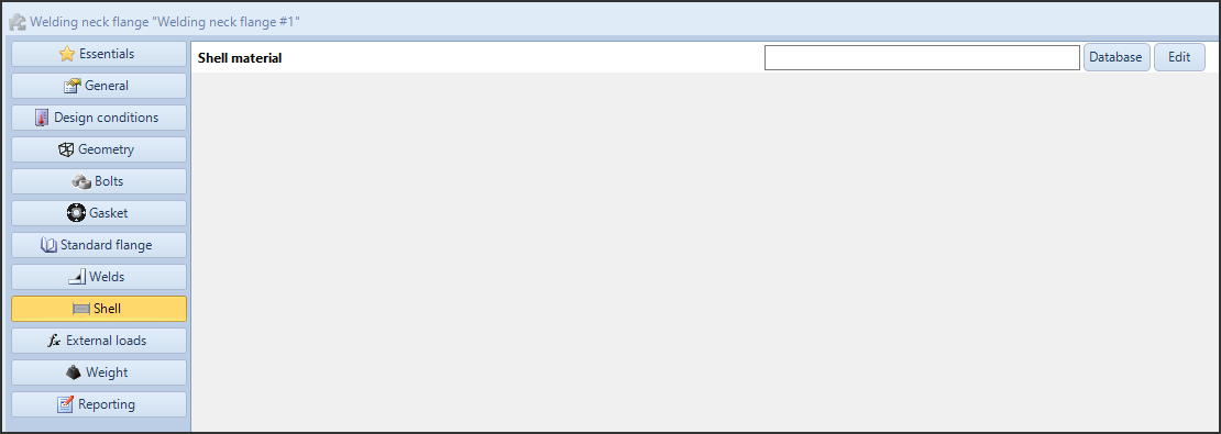
_ A Welding Neck flange designed as an additional component requires the shell material, which is not an input in the 3D view_
Participation in general device properties
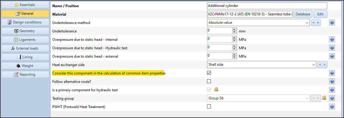
In the "General" category there is a checkbox "Consider this component in the calculation of common item properties": this option tells the program whether this component should be considered in the calculation of general device properties, such as weight and hydraulic test pressure.
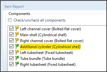
Additional components are shown in italics in the print list. In the report, there is no difference between the report of a 3D component and the report of an additional component.
Components without 3D interface
Some components are completely devoid of the possibility of being represented in 3D, either because the model is complex, or because they are simply abstractions.
When the user selects a component of this type, the program warns of the need to insert the component in question via the Desktop View.

The dialog box that appears when the user tries to add a component that cannot be represented in the 3D view
Such components are for example:
- Clamp connection (ASME)
- Simplified fatigue analysis (EN and AD)
- Detailed fatigue analysis (EN and AD)
- Fatigue screening (ASME)
Heat Exchangers
Designing an exchanger with NextGen involves using and compiling the Heat Exchanger Wizard. At the end of this process, the exchanger is modeled in its entirety, complete with plates, tubes, shell, and cases.
If the user wishes, when prompted to compile the Heat Exchanger Wizard, he can choose to cancel the operation, finding himself in front of the empty workspace of NextGen. At this point, he can switch to the Desktop View and add only the tube sheet and exchange tubes elements.
The calculation of the tubesheets cannot proceed before the tubes bundle is also added, and vice versa.
This allows for a faster and simpler calculation, covering cases that do not belong to the classic TEMA configurations.
News archive
- Jan 07, 2025: Understanding and solving validation warnings
- Nov 11, 2024: How to create an additional component with the "Desktop View"
- Sep 24, 2024: Understanding and solving validation errors
- Jun 12, 2023: NextGen 2023 user interface guide
- Jan 01, 2017: Getting started step-by-step guide