Expansion joints
Expansion joints (also known as expansion bellows or compensators) are used in fixed tubesheets heat exchangers to reduce thermal stresses in the case of high temperature differences between the two sides. The program offers three different methods to consider an expansion joint.
Option 1: Entering only the expansion joint main properties, without creating the model
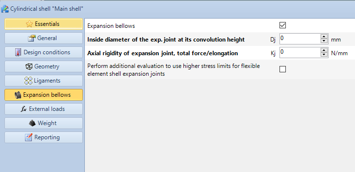
In the calculation of fixed tubesheets, only two expansion joint properties are usually required, namely the maximum internal diameter and the axial stiffness. These values are usually provided directly by the manufacturer. It is therefore possible to enter only these two properties without having to add the expansion joint as a component for code verification. In the Heat Exchanger Wizard it is sufficient to enable the appropriate option and enter the two values, as shown in the figure.
This is the most approachable scenario for users purchasing a ready-made expansion joint from a third-party supplier
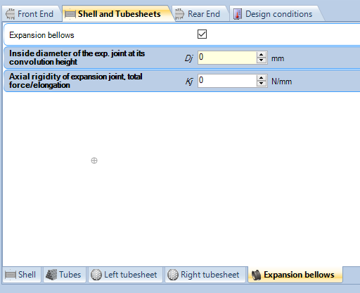
After running the wizard and creating the heat exchanger, the properties of the joint will be visible in the Shell tab. It is also possible to add them directly to the shell after running the wizard, if they have not already been inserted previously.
Option 2: Inserting the dilator as a 3D component
If you also need to perform or verify the calculation of the expansion joint, you can add it as a physical component to the heat exchanger model, after the Heat Exchanger Wizard has been executed. To do this, simply right-click on the main cylinder and select the appropriate "Insert expansion joint" option:
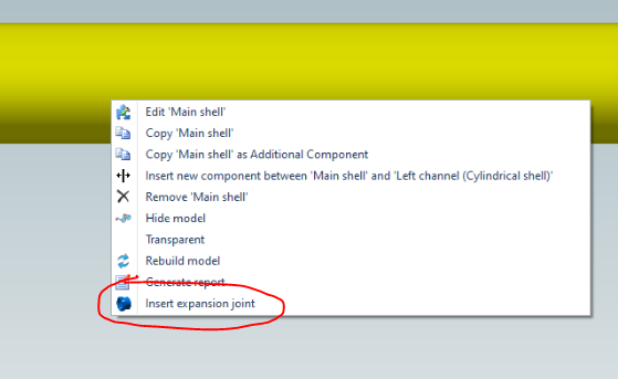
The input window for the properties of the joint will open, you can enter all the required data here.
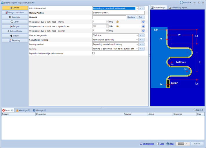
It is possible to perform the calculation of the expansion joint according to the method provided by the selected calculation code, e.g. Appendix 26 for ASME VIII Div. 1, Chapter 4.19 for ASME VIII Div. 2, Clause 14 for EN 13445-3, or according to EJMA 10th, if the calculation module is present in your license. The method selection is possible in the first property "Calculation method". The program provides for the verification of "Unreinforced U-shaped bellows" type bellows and does not support the verification of toroidal or ring-reinforced joints. Also note that the verification of the joint may require, depending on the selected calculation method, values that can only be calculated through a fatigue calculation of the device.
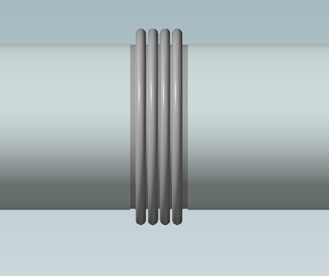
At the end of the insertion, the component will be inserted in the center of the shell, which will thus be divided into two equal parts.
The tubesheet calculation module will automatically take into account the presence of the expansion joint, whether it was inserted according to point 1 or whether it was inserted as a component according to point 2. Note that inserting the properties in the Shell tab (option 1) takes precedence over creating the model as a physical component (option 2)
Option 3: Inserting the expansion joint as an additional component
If you only need to check the joint or if you do not want to add it as a physical component to the exchanger, you can add it as an additional component. In this case, the properties of the joint will have to be filled in manually. There will be no interaction between the expansion joint thus designed and the rest of the calculation.