Understanding and resolving validation warnings
When designing with NextGen, it is perfectly normal and common to receive validation messages, highlighted in yellow, called warnings.
A calculation subjected to validation and containing warnings can be considered generally valid in compliance with the calculation code.
Why is it specified as generally valid? Because the warnings themselves can contain information on assumptions made by the program, for example due to a lack of more specific data, which limit the validity of the validation. A scenario of this type is shown below.
It is always recommended to carefully read the warning message, deepening where possible through the specific paragraph of the calculation code cited in the message itself.
This article provides the information needed to independently manage the warnings and to use them to your advantage.
Difference between errors and warnings
The specific characteristics of validation errors can be consulted in this article. The main differences between errors and warnings are the following:
An error determines the invalidity of the calculation, a warning does not
Errors are always printed, warnings can be omitted from the report
Errors must be resolved, warnings can be resolved or, alternatively, accepted and hidden.
Resolution of a warning
Some materials are supplied with different mechanical characteristics based on their thickness: it can therefore happen, for example, that a 10 mm sheet and a 30 mm sheet made of the same material have different yield strength, tensile strength and therefore allowable stress characteristics.
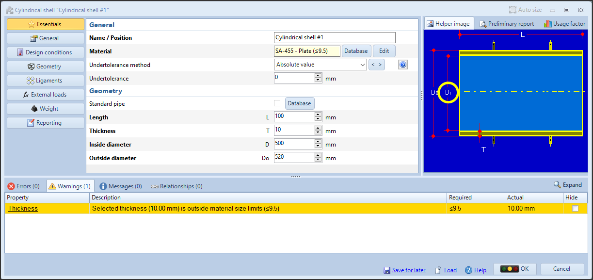
In this example, a cylinder with a nominal thickness of 10 mm has been made, but the selected material is indicated for thicknesses less than or equal to 9.5 mm.
Therefore, the program warns the user with a message.
The calculation itself cannot be considered incorrect, since the user may have his reasons for using a certain material anyway and, basically, by applying the validation rules and taking into account the input data, the cylinder in question is stable.
This type of warning is easily solvable by intervening on the input data itself, choosing a material suitable for the nominal thickness in use.
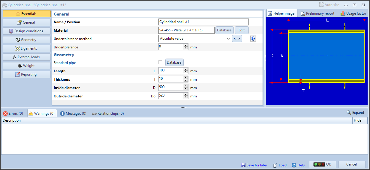
Choosing the next group of thicknesses (between 9.5 mm and 15 mm), the warning is no longer displayed.
Accepting a warning
The example reported above concerned an easily resolvable warning. In some cases you may find yourself faced with a warning that you cannot, or do not want to, resolve by acting on the input.
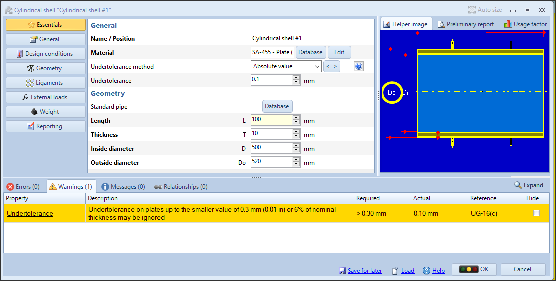
For the cylinder in question, a tolerance on the plate equal to 0.1 mm has been specified. In the context of ASME VIII Division 1, this value can be ignored, since it is less than 0.3 mm. It would of course be possible to change the tolerance to the value 0 mm, eliminating the warning, but if - for example for order needs - you still want to keep this value, the checkbox in the "Hide" column comes to our aid, allowing us to hide (or, accept) the warning, ignoring it in the validation and restoring the green traffic light.

By clicking on the checkbox, we tell the program to ignore that specific warning. By right-clicking on the same checkbox, we get a pop-up menu where we can not only perform the previous operation but also specify to ignore the same warning for all present and future instances in the current calculation.
The message presented in the example would appear in all the components of the calculation with a tolerance lower than 0.3 mm: using "Hide for entire item", all warnings of this type will be hidden automatically.

When a warning is hidden, it appears gray. If a calculation is error-free and all its warnings are hidden, the traffic light appears green.
Warnings hidden via this procedure are also excluded from the calculation report.
Advantages of managing warnings
By exploiting the behavior of warnings and the influence that these have, together with errors, on the traffic light that identifies the validation status of components, it is possible to organize your workflow in order to keep the validation status under constant control as the project evolves.
A tree view of the components is shown on the left side of the program window, whose icon color reflects the color of the traffic light in the corresponding validation window.
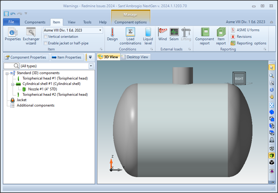
In an ideal situation, we will have all the components indicated in green, which denotes the absence of errors and warnings (or, that all the warnings have been managed).
It may happen that the addition or modification of a component, or the modification of design conditions, has a direct influence on the validation of all or part of the other components: for example, by varying the hydraulic test pressure in this ASME VIII Division 1 calculation and entering a manual value, once the complete validation is forced all the components present a new warning and go into yellow status.
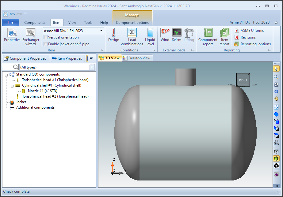
Reopening the cylinder for editing, you can see that the previous hidden warning is joined by a new one, relating to the manually specified hydraulic test value.

Having previously all the components indicated with a green icon allows you to intercept the onset of a new warning to manage as soon as possible. If the components had already been indicated in yellow, we would not have been able to receive a visual indication of the increase in warnings.
Warning that indicate particular assumptions adopted by the program
It may happen that in order to continue with a calculation, NextGen must make specific assumptions, otherwise it will not be possible to execute it. These considerations are highlighted as warnings and must be carefully evaluated because, as indicated in the initial premise, the calculation is to be considered valid if these assumptions are true: this can lead to a deviation from the input data indicated by the user.

The WRC bulletins have particularly restrictive requirements, which would make them inapplicable in the majority of cases. In order to proceed and perform the analysis by formulae of the local stresses, NextGen indicates these limitations as warnings.
In these cases, the user is responsible for establishing whether, for the requirements of the parties involved (internal practices, requests from the client, assessments with the Authorized Inspector), the assumptions made by NextGen are acceptable or not.
In most cases where these considerations are not considered valid, it will be necessary to proceed with an alternative calculation, for example by adopting a different Calculation Code or by performing a Finite Element Analysis.
Additional information
Print options
In the print options of the calculation report, under the "Components" category, there is a checkbox that allows you to control the printing of validation warnings.
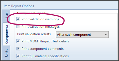
As previously mentioned, hidden warnings (for the single component or the entire device) are automatically excluded from the report. By unchecking the "Print validation warnings" box, all warnings will be excluded from the report.
Reset the visibility status of all warnings
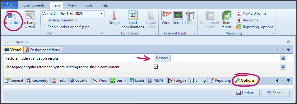
If you wish to make all the warnings for the current project visible, you can open the Item Properties, head to the Options section then click the "Restore hidden validation results" button.
Behavior of hidden warnings in multi-language environment
The function that allows to hide the warnings described above is based on the text of the message contained in them. For this reason, if you use the program interface in one language, for example English, and you produce the calculation report in a different language, for example German, the calculation report will not be able to hide the warning messages automatically. In this case, you can proceed in the following ways:
Disable the printing of warnings in the printing options, as described above
Align the interface language (File, Options, General, Input language) to the language used to produce the calculation report, if possible