Positioning of nozzles and other secondary components
NextGen positioning system up to and including version 2024.0
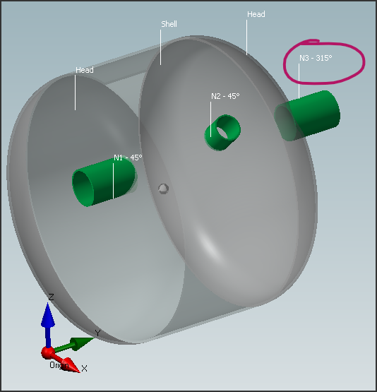
Historically, NextGen had an arbitrary positioning system, not modifiable by the user. The main limitation of this system was the rotation of secondary components, such as nozzles: in particular, for a device with two bottoms, in order to obtain an alignment between the nozzles positioned on one and the other bottom, it was necessary to "mirror" the angle between them, deviating from the dimensions in the drawing.
For example, in the following image, nozzle N3 has an angle set to 315° to keep it aligned with nozzles N1 and N2 angled at 45°:
This issue has been resolved starting from version 2024.1, while still allowing the user to keep the previous positioning for backwards compatibility.
Options related to the rotation (angular offset) of the secondary components
Within the properties of the Item, in the Options category, it is possible to set the positioning options for the calculation:
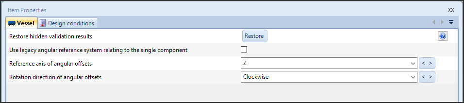
For all the Item created with versions prior to 2024.1, NextGen automatically enables the backward compatibility (legacy) option. For new calculations instead, the Z reference axis is set and the direction for the rotation of the angular offsets is set to clockwise.
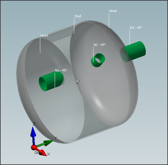
At this point, the angular positioning of the nozzles in the example file is congruent, all the nozzles have an angular offset of 45° and are visually aligned.
Choosing a reference system equal to the one used in the drawing allows for continuity between the drawing and the calculation report, with the same angular dimensions reported on both documents.
Linear positioning (linear offset) of secondary components
The linear positioning of components occurs through the distance between the reference point of the component we want to position, for example the axis of the nozzle, and the edge of the component on which it is applied.
In general, NextGen references go from right to left for horizontal devices and from bottom to top for vertical devices.
There is an option that facilitates positioning if the drawing dimension available to us is the distance from the origin:
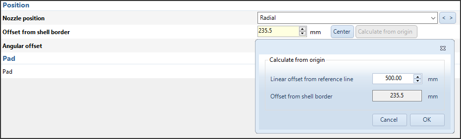
By entering the distance from the origin, the distance from the edge of the component will be automatically calculated.
Nozzle height definition
By default, to define the nozzle height the program requires you to enter the length of the pipe:
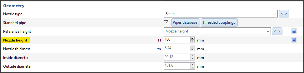
When the drawing of the device contains different dimensions, usually measuring the distance between the axis of the shell and the face of the flange applied to the nozzle (or, in the case of heads, between the tangent line and the face of the flange), it is sufficient to modify the option relating to the Reference height:

By doing so, the input required will be the projection (from the axis or from the tangent line depending on the type of component to which the nozzle is being applied). The program will automatically calculate the length of pipe needed to maintain the entered dimension once the relative flange has been added.
News archive
- Oct 17, 2024: NextGen 3D modeler
- Oct 14, 2024: Nozzles and other secondary components positioning
- Oct 05, 2021: The item properties window
- Feb 01, 2019: The components design window (component properties)
- Feb 17, 2017: How to set different pressures on adjacent components
- May 05, 2016: How to manage geometric relationships between components
- Jun 26, 2015: How to backup customized elements
- Sep 02, 2014: How to set item service according to UG-16