NextGen 3D modeler
Introduction
The final product of a software for the design of pressure vessels is the calculation report, a report that mathematically demonstrates that the rules defined in the reference standards are satisfied.
Sant'Ambrogio has been producing programs for the calculation of vessels and exchangers for over thirty years and the first iterations of these programs were essentially composed only of the numerical input of the dimensions of the pressure parts.
The advent of more modern computers, capable of showing on video the representation of what is the pressure vessel being designed, has offered users the possibility of obtaining a more faithful image of what they are processing, reducing positioning errors and favoring the navigability of the project.
This is a particularly welcome aid by users, although not essential.
Even today it is perfectly common to carry out calculations of pressure parts using Excel, a tool completely devoid of a graphical representation of what is being designed.
NextGen has its way of calculating components outside of the 3D environement in its "Desktop View"
Purpose of the 3D view in NextGen
The 3D view in NextGen offers the possibility of navigating your equipment model in a simpler and more intuitive way than just the list of components that make it up.
It allows you to easily see the positioning of secondary components, such as nozzles, long welding neck flanges and other connections.
It also allows you to get an idea of the proportions of the final product.
Differences with a CAD
In the case of a software for assisted technical drawing, known as CAD, the purpose of the application is to produce a model as faithful as possible to the reality of the object being designed. For this reason, the features available within the CAD are completely oriented towards facilitating the user in achieving this goal.
What is present in NextGen is instead oriented towards performing a calculation in code, supporting the user with all the visual tools available but without forgetting the initial objective, which is and remains the production of the calculation report.
Model fidelity
The 3D model displayed by NextGen is based on the input provided by the user in the component design window. In that context, the user is asked for all the data necessary for the calculation of the pressure or structural part. To simplify the user's work, NextGen does not require data that is not functional to the mechanical calculation: in some cases, this can lead the 3D modeler to not have enough data to resolve ambiguities and represent the component with a different shape than the real one.
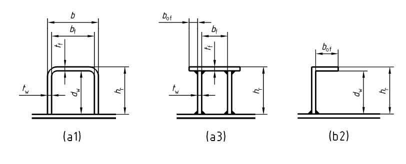
An example concerns external reinforcements, which can be used on rectangular devices or on flat covers.
Such reinforcements can have a wide variety of shapes and to obtain a faithful model it would be necessary to ask the user for a considerable amount of data that is not functional to the calculation, with the risk of producing something different from the final product.

Some of the possible reinforcement configurations for rectangular vessels

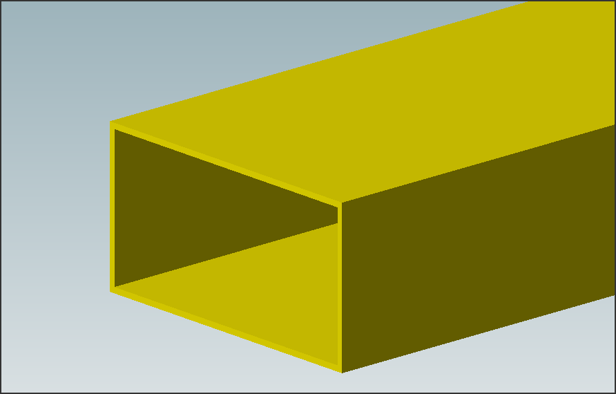
The 3D model of the externally reinforced rectangular appliance is displayed without the external reinforcements
Performance
In some cases, when drawing the 3D model of some components, there are choices made by Sant'Ambrogio with a view to optimizing performance.
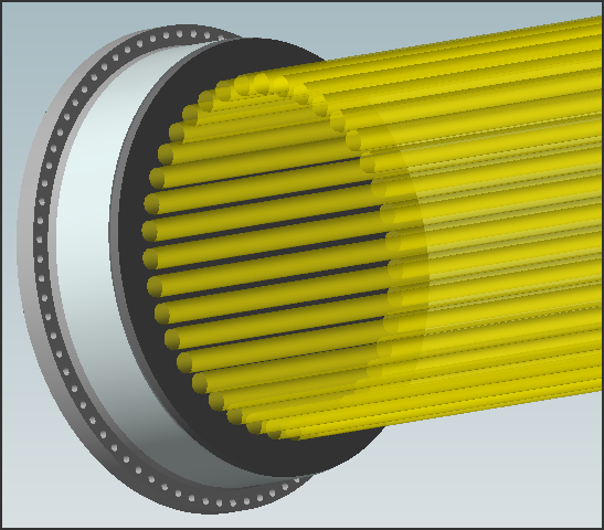
For this reason, some components, especially if internal as in the case of a tube bundle, are drawn partially. It is not functional to the purpose reported above to draw hundreds of tubes - which would significantly and unjustifiably weigh down the model - when a partial rendering is sufficient.

The tube bundle of this vessel is defined with 180 tubes: only the outer ring of tubes is rendered, which shows the user the overall footprint and allows easy selection for modification. Drawing the inner tubes would create a heavier model without any real benefit for the purpose of NextGen.
Conclusions
Although the presence of a 3D modeler within the program may mislead as to the final purpose offered, the primary focus of NextGen is on the calculation of pressure vessels and the production of a complete, readable and reliable report. The 3D model is available as an aid to the designer and, in some cases, may not represent the vessel in its actual form.
Search the documentation
Customer area
Categories
Articles in this category
- The item properties window
- The components design window (component properties)
- NextGen 3D modeler
- Nozzles and other secondary components positioning
- How to set different pressures on adjacent components
- How to manage geometric relationships between components
- How to backup customized elements
- How to set item service according to UG-16