How to manage geometric relationships between components
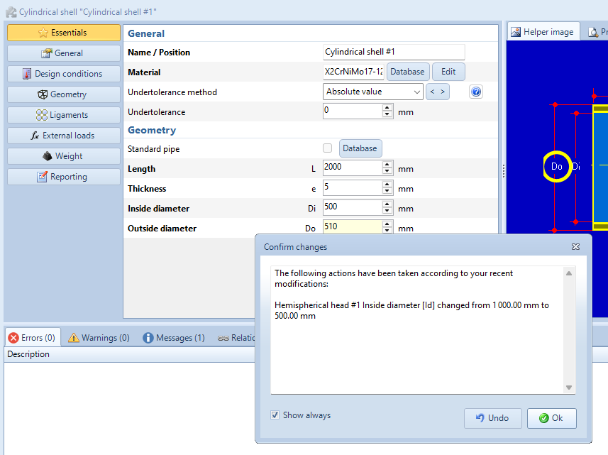
By default, NextGen takes care of maintaining geometric relationships between components of an item. For example, when a vessel made of a cylinder and two heads having inside diameter 1000 mm is made and later cylinder inside diameter is lowered to 500 mm, NextGen resizes adjacent heads to keep vessel's shape congruent. The software shows a message like the following to notify the user:

There are cases when this behavior is not necessary or wantet; here's a couple of options to disable it.
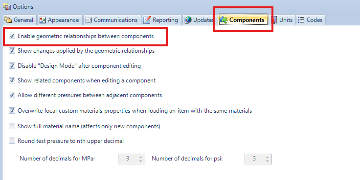
Completely disable geometric relationships
Relationships can be disabled completely by selecting Tools > Options and then unchecking "Enable geometric relationships between components under "Components" tab. This way, the user have complete control over items geometry, including type and number of bolds and gaskets in flange joints.

Partially disable relationships
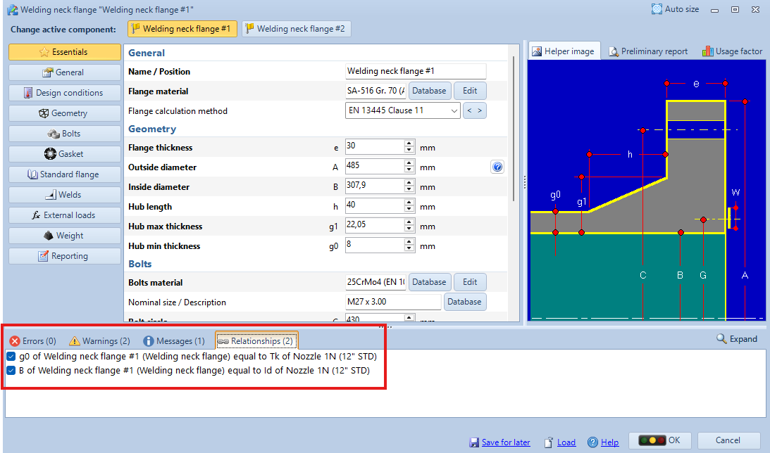
In cases when only one or few relationships must be disabled, a "Relationships" tab can be found in the component editing window (this tab is visible only when the checkbox "Enable geometric relationships between components" is enabled): from this tab an accurate control over single relationships is possible, enabling or disabling them at wish.
A relationship is defined when a component is connected to another. For example, in a cylinder-flange-blind flange vessel, cylinder will not list any relationship, flange will list relationships with cylinder (g0, inside diameter), blind will list relationships with flange (bolts, gasket). These are bi-directional relationships, so if cylinder thickness is modified, g0 of flange will be modified too. Therefore, it is better to look at both components when a relationship must be disabled.

Search the documentation
Customer area
Categories
Articles in this category
- The item properties window
- The components design window (component properties)
- NextGen 3D modeler
- Nozzles and other secondary components positioning
- How to set different pressures on adjacent components
- How to manage geometric relationships between components
- How to backup customized elements
- How to set item service according to UG-16