Item properties setup
In this article we will analyze the properties available in the window “Item properties”, accessible from the “File” menu. This window is also the first window shown to the user at the creation of a new file.
Premises
This article is being completed: If you need an explanation for an option that is not in the article, please contact us through the usual assistance channels.
The list of properties is continually updated. This article refers to the version 2022.2 of the software.
The list of properties may vary between different calculation codes.
The list of properties may vary between vessels and heat exchangers.
General
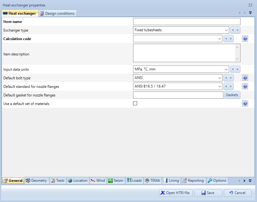
General section for a heat exchanger
Exchanger type
Type of exchanger you want to design
Calculation code
Calculation code used to validate the item. Codes listed in bold are the latest available versions when the version of the software currently being used was published.
Codes listed here are those available within your license. Please note that some codes may have been disabled: to manage disabled calculation codes, select Tools > Options > Codes.
Item description
This property can be used to provide a description for the item.
Input data units
Choose whether you'd like to input data in metric or customary units
Default bolt type
This option determines which type of bolt (ANSI or ISO) is used by the software when designing bolted components and the user has not already selected any bolt.
In a similar way, a default standard for nozzle flanges and a default gasket for nozzle flanges can be selected.
Use a default set of materials
Apply a default set of materials to this item. When a default set of materials is selected, components' materials are automatically selected by product form.
Geometry
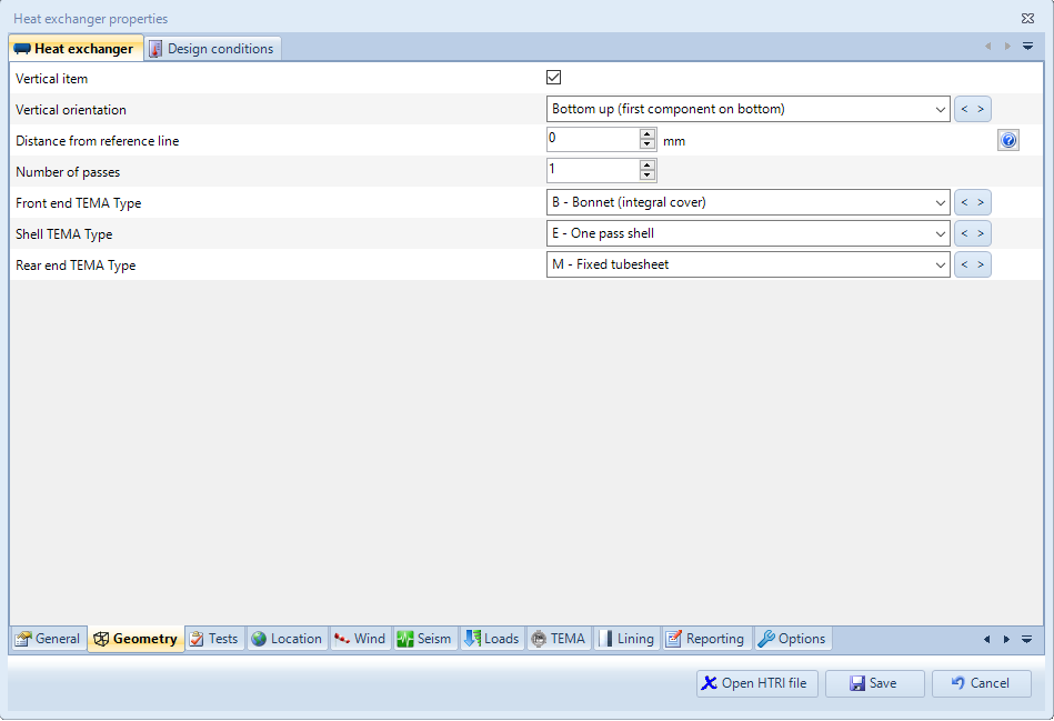
Geometry section for a heat exchanger
Vertical item
Sets the item as vertical. This option is used by the software for the automatic calculation of the hydrostatic head, it’s therefore important to specify correctly the orientation.
Internally NextGen manages the connection between components form left to right when the item is horizontal and from bottom to top when the item is vertical.
Vertical orientation (only for heat exchangers)
A vertical heat exchanger can be set “bottom up” or “top down”. In the first case, the main tube sheet is positioned at the bottom, in the second case the main tube sheet is positioned at the top.
Distance from reference line
Indicates the distance between the ground line and the lowest part of the first main component (thus excluding the nozzles). This option is useful for communicating to NextGen that the item that is being designed is not positioned on the ground but in an elevated structure. This distance is taken into account when calculating the wind profile and the period of vibration.
Number of passes (only for heat exchangers)
Number of passes in a heat exchanger.
Front end TEMA type (only for heat exchangers)
Left head configuration for a heat exchanger, according to TEMA nomenclature. The available options can change depending on the type of the heat exchanger that is being designed.
Shell TEMA type (only for heat exchangers)
Shell configuration for a heat exchanger, according to TEMA nomenclature.
Rear end TEMA type (only for heat exchangers)
Right head configuration for a heat exchanger, according to TEMA nomenclature. The available options can change depending on the type of the heat exchanger that is being designed.
Tests
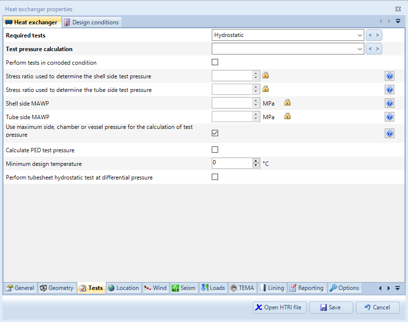
Tests section for a heat exchanger
Required tests
You may choose to apply a hydrostatic test, a pneumatic test, or both.
Perform tests in corroded condition
Usually testing is performed when the item is new and hence not corroded, this is also the default behavior of the software. Enable this property if you wish to perform tests in corroded condition.
Stress ratio used to determine the shell/tube side test pressure
The stress ratio used to determine the test pressure is automatically calculated by the software, but a custom value may also be provided by the user (for example for taking into account the influence of components that are not present in the item) by clicking on the padlock icon.
Shell/tube side MAWP
Use this property to define a specific value to be assumed as maximum allowable working pressure for a vessel, heat exchanger side or jacket. The value defined here overrides the one calculated by the program.
Use maximum side, chamber or vessel pressure for the calculation of test pressure
When this option is checked, the pressure used as base for the calculation of the test pressure for a vessel, the chamber of a jacketed vessel or the side of an heat exchanger will be the maximum specified for the components belonging to that vessel, chamber or side. When unchecked, each component will use its own specified pressure. Be aware that this may lead to wrong overall test pressure value when different components have different specified pressures.
Location
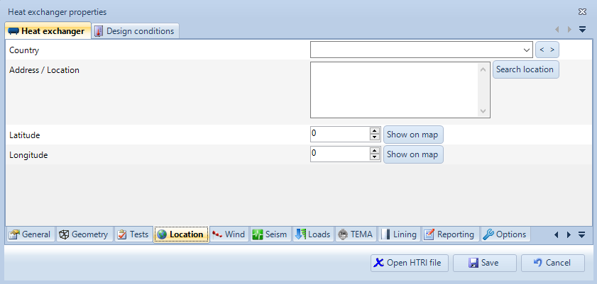
Location section
In this section it is possible to choose the location of the item being created. This can be particularly helpful when using the italian wind code, the "wind zone" requested by the software can be automatically calculated based on the location of the item. By clicking on "Search location", it is possible to choose the location directly on the map.
Wind
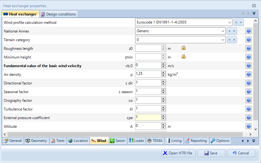
Wind section
In this section it is possible to choose a method for calculating the wind profile that the item will be subjected to. Inputs vary depending on the chosen wind profile calculation method.
Seism
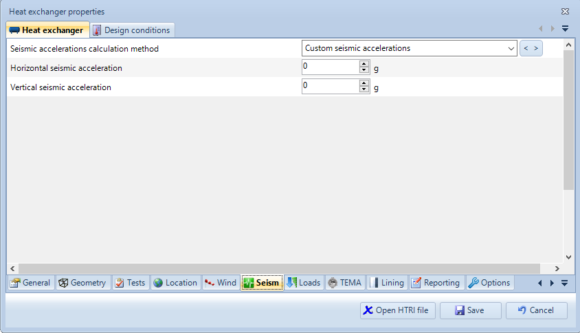
Seism section
Similarly to the wind section, different methods are available for calculating seismic accelerations. Inputs vary depending on the chosen method.
Loads
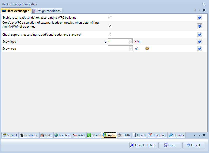
Loads section
Enable local loads validation according to WRC bulletins
When this option is checked, a new category will be shown on nozzles and attachments, allowing the user to validate local loads and stresses according to applicable WRC bulletins. This feature is subject to license limitations.
Consider WRC calculation of external loads on nozzles when determining the MAW(P) of openings
When this option is checked, the WRC external loads validation is taken into account (when enabled) for the determination of the maximum allowable working pressure
Check supports according to additional codes and standards
Supports can be calculated with additional codes and standards, e.g. Bednar Handbook, Roark, NTC: when this option is checked, these codes will be activated and validated. When this option is disabled, validation will be done by using only current calculation code if a method is present. This feature is subject to license limitations.
Snow loads
Characteristic value of snow load, may be found in the national annex or on public websites
Snow area
This property can be used to define a specific value to be assumed as the vessel area in which the snow load is applied (overriding the value calculated by the program)
Search the documentation
Customer area
Categories
Articles in this category
- The item properties window
- The components design window (component properties)
- NextGen 3D modeler
- Nozzles and other secondary components positioning
- How to set different pressures on adjacent components
- How to manage geometric relationships between components
- How to backup customized elements
- How to set item service according to UG-16