How to design a hairpin or double pipe heat exchanger
The Heat Exchanger Wizard available in NextGen allows the design of heat exchangers of the types defined in the TEMA standards. For special cases, such as for the exchangers in question, it is necessary to proceed using the single-component design mode, alongside the usual 3D model.
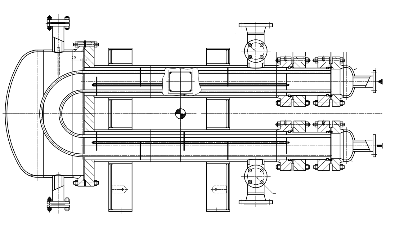
An example of a hairpin exchanger design is shown below:
Definition of the model and design conditions
Let's start as usual by creating a Heat Exchanger, selecting the reference standard and selecting "U-tubes" as the type of exchanger. We define the design conditions exactly as for a TEMA exchanger, with pressures and temperatures for the tube side and shell side.
When the file is saved, since the item is an heat exchanger, the Heat Exchanger Wizard screen is shown: you can close this window and cancel the guided creation of the exchanger.
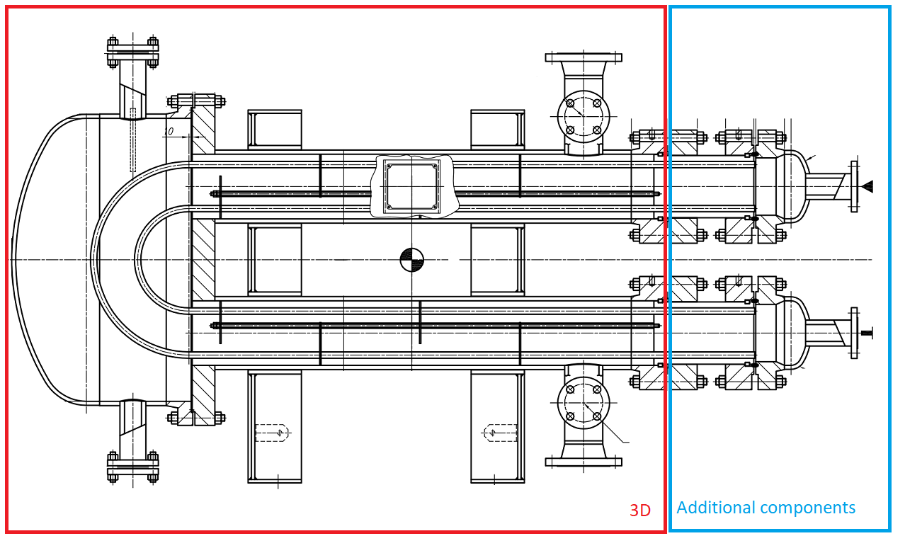
We divide the exchanger into two parts, a first part that can be designed with a 3D model and a second part for which we will use the additional components.
3D modeling of the main body for the shell side
Following the example of the proposed design, the 3D model of the left section is simple: the main body is composed - from left to right - of a rounded bottom, cylinder, flange, bolted flat cover with two set-on nozzles: with the two openings on the lid we calculate the shells making the two "legs" of the exchanger and their opening reinforcement.
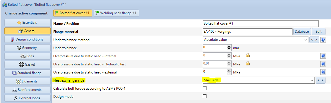
Having initially closed the Heat Exchanger Wizard, it is necessary to give a manual indication of the side to which the various components belong: it is possible to do this, for each of them, using the appropriate drop-down control.
Definition of additional components for tube side, plate and tube bundle
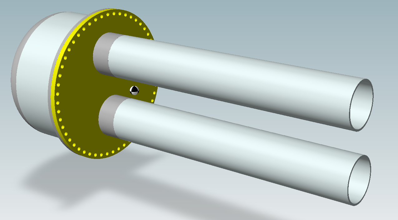
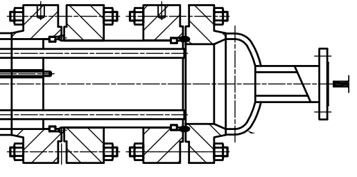
On the tubes side we find two welding neck flanges to be calculated, visible in the following image (one for the pipe side and one for the shell side) and the relative counter flanges.
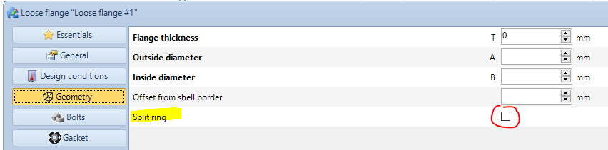
For counter flanges, if they are made up of two halves, select the "Split ring" option in the "Geometry" category. Associate the correct exchanger side. Again for the counter flanges, it is necessary to manually set the pressure equal to zero and the load on the bolts by reading it from the calculation of the respective flanges.
For some configurations, the counter flanges are absent: in this case it is sufficient to model only the flanges on the pipe and shell side that grip the tube plate.
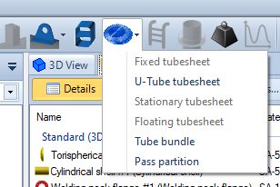
The bonnet and opening components are designed as usual. The tubesheet must be added again as an additional component, by selecting the appropriate item from the top menu:
Some notes:
The calculation of the tubesheet inserted as an additional component depends on the presence of a tube bundle. Both components must be added before the stability can actually be verified
The tubesheet of a U-tube exchanger normally requires the insertion of the number of hairpins, therefore a value equal to half the number of holes. Since in this case the hairpins start from one tubesheet and end in another, it is necessary to adjust the input in order to obtain an adequate number of holes.
Variations for a double pipe exchanger
Unlike the hairpin, the double pipe does not require the presence of a tube bundle; what plays the role of tubesheet is then a simple metal ring.
It is no longer necessary to calculate the device as a heat exchanger, it is possible to use a simple vessel. Calculating as an exchanger, you have the advantage of having two independent pressure and temperature zones automatically managed by NextGen; in case of vessel, pressure and temperature (with particular attention in case of vacuum in the chambers) must be managed manually. A further option is to calculate everything as a jacketed vessel.
For the calculation of the single internal tube we proceed by creating a cylinder as an additional component, verifying that the internal and external pressure values are adequate.
For the calculation of the ring / tubesheet we can insert a "welded flat cover" as additional component, setting it as non-circular, entering the average circumference of the circular crown that constitutes the cross section as large span and the difference between the greater and smaller radius as short span. The idea is to calculate a rectangular surface that is the unwinding of the circular crown.
Search the documentation
Customer area
Categories
Articles in this category
- Design a body/girth flange automatically using the Flange Designer tool
- How to design an hairpin or double pipe heat exchanger
- How to design a vapor belt for an heat exchanger
- How to design a double tubesheet heat exchanger
- Low temperature design according to AD 2000 code
- Design of adjacent VSR openings beyond 0.8 De of a formed head
- Fatigue Analysis Screening, Method B according to ASME Section VIII div 2 Clause 5.5.2.4
- Using the Usage Factor function to calculate the percentage of component utilization
- PED compliance for equipments designed according to ASME
- Maximum Allowable Working Pressure (MAWP) and hydrostatic test pressure calculation
- Vortex shedding calculation according to EN13445 Clause 22.10
- Clamp connections
- Item revision system
- How to design supports for stacked equipments