How to design a double tubesheet heat exchanger
By following the requirements TEMA RCB-7.1.2 it is possible with NextGen to calculate heat exchangers equipped with double tubesheets.
Simplified analysis
The calculation in NextGen assumes the presence of a single tube plate. The simplest approach is to calculate the single plate that needs greater thickness within the 3D model; generally, this plate corresponds to the external, flanged one: the same thickness will be adopted for the tube plate welded during construction.
Complete analysis
This assumption is valid for tubesheets of the same material and without substantial geometric differences and design conditions between the two sides: for a more complete verification, which covers more complex scenarios, you can use the following approach.
You can model the exchanger via the Heat Exchanger Wizard with the configuration welded on the shell side and bolted on the tube side; the design condition for this configuration will be that with full pressure on both the tube side and the shell side.
Next, you can add an additional tube sheet as additional component, which you will configure as an integral tube sheet on both sides.
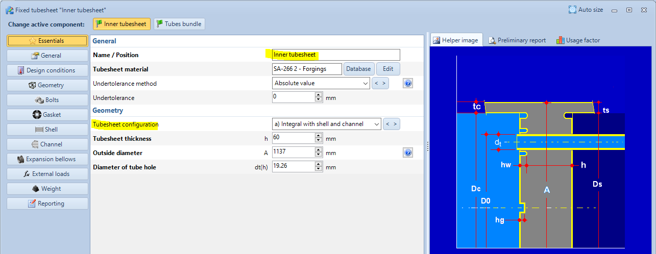
This tubesheet will automatically use the tube bundle defined in the 3D view and may have different geometric and material characteristics from the "external" plate.
In some cases it is not possible to completely exclude the presence of shell or channel in the calculation of the tubesheet, since there are (for example in ASME) minimum dimensions for these components. It will therefore be necessary to make some assumptions in this regard.
Further refinements
The presence of two separate plates entails the lack of some scenarios foreseen by the Loading Cases present in the standards (ASME, EN 13445): if you deem it appropriate, you can manage to exclude the non-applicable Loading Cases by modifying the characteristics of the tubesheet:
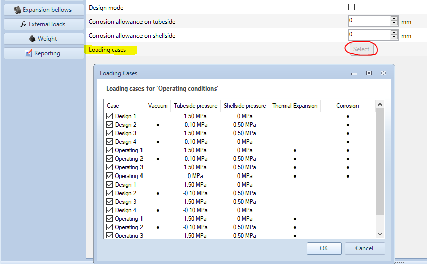
This option is to be evaluated in particular with the presence of the vacuum, in cases where the Loading Case that considers the vacuum becomes the determining one.
A further tool available to cover more complex cases is the possibility of defining different design conditions within the Item Properties: NextGen will verify all the conditions simultaneously and you will give you the possibility to print the reports of the entire item or individual components corresponding to a specific design condition.
The procedure reported here is to be understood as a suggestion, derived from the Sant'Ambrogio experience: you should evaluate it according to your own experience and the opinion of your Authorized Body.
Additional calculations
NextGen does not natively cover all the calculations you need to perform in this scenario.
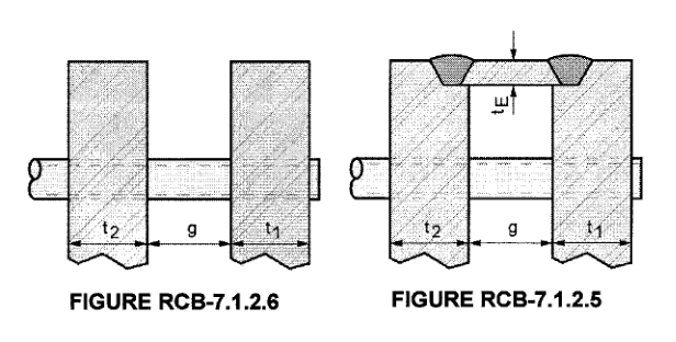
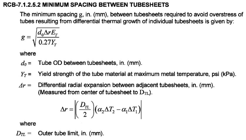
TEMA requires a minimum distance between the two plates (distance "g") according to RCB-7.1.2.5.2 and RCB-7.1.2.6.2 equal to:
In the same way, it defines the calculation of the minimum thickness of the joining element between the tubesheets, when present. Please refer to the norm for the details of the calculation, remembering that it is possible to insert calculation notes in NextGen reporting the results of these equations, by modifying the component in its "Reporting" section.
Search the documentation
Customer area
Categories
Articles in this category
- Design a body/girth flange automatically using the Flange Designer tool
- How to design an hairpin or double pipe heat exchanger
- How to design a vapor belt for an heat exchanger
- How to design a double tubesheet heat exchanger
- Low temperature design according to AD 2000 code
- Design of adjacent VSR openings beyond 0.8 De of a formed head
- Fatigue Analysis Screening, Method B according to ASME Section VIII div 2 Clause 5.5.2.4
- Using the Usage Factor function to calculate the percentage of component utilization
- PED compliance for equipments designed according to ASME
- Maximum Allowable Working Pressure (MAWP) and hydrostatic test pressure calculation
- Vortex shedding calculation according to EN13445 Clause 22.10
- Clamp connections
- Item revision system
- How to design supports for stacked equipments