Design of adjacent VSR openings beyond 0.8 De of a formed head
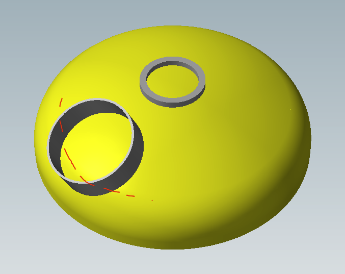
A common usage scenario for a formed head in the upper part of a vessel is the one with a reinforced ring positioned centrally, for example to attach an agitator, with a manhole that partially straddles the knuckle, the toroidal area of the bottom.
Concerning the calculation of the two isolated openings we do not encounter particular problems, but things get complicated when these two openings have their respective reinforcement areas overlapped: in this scenario it is necessary to perform the calculation of adjacent openings, defined in the paragraph VSR.1.K .4
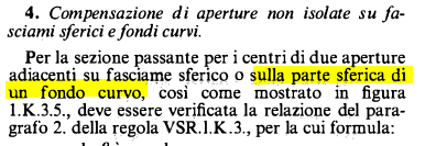
The paragraph limits the applicability to the presence of two openings on the spherical part of the head and the standard does not provide indications on how to proceed in case of openings partially or totally positioned on the toroidal part.
In our experience as a design company we have seen several methods to get around this problem and from NextGen version 2021.2 it is possible to take advantage of the limitation of the reinforcement on the head to get out of this impasse.
When the problem occurs
Imagine such a scenario: two, or more, of the inserted nozzles are positioned astride the bottom knuckle
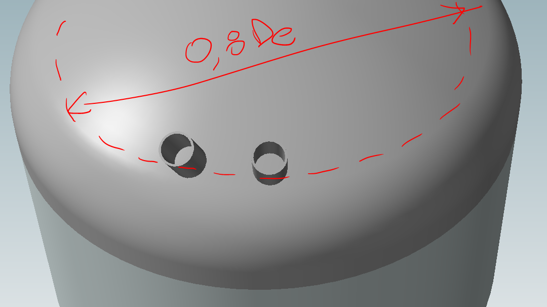
Since their reinforcement limit on the bottom overlaps, the standard imposes at this point the calculation of adjacent openings:
The limit of the reinforcement is defined in VSR.1.K.3 1.2 and is equal to √[(2·ri+s)·s]
Upon encountering this configuration, NextGen shows the following error:
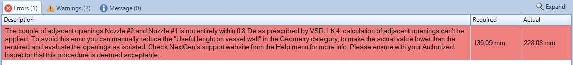
The required and actual values shown refer to the geometric distance between the centers (required) and the sum of the radii and horizontal reinforcement limits measured on the line joining the two centers
How to get around the problem
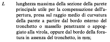
What can be done is to manually limit the length on the head that contributes to the reinforcement, defined as L in the standard
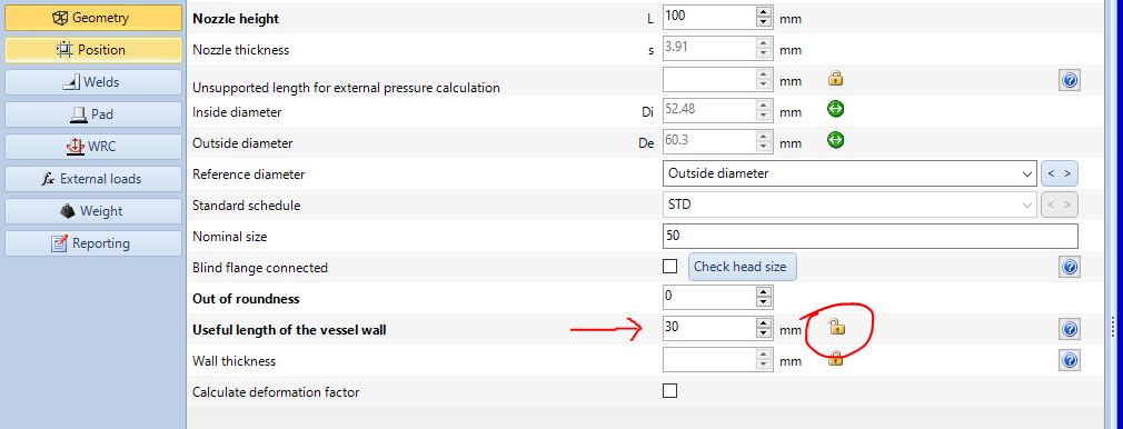
To do this, simply unlock the padlock icon located next to the Useful length of the vessel wall property, then enter a manual value.
In the error message, the difference between the requested and the current value can help you get an idea of how much this size needs to be reduced to avoid the error. Naturally, this operation involves a lower contribution of the bottom material for the purposes of compensation, which will weigh more on the nozzle.
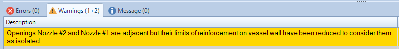
Once there is no more interference between the two openings, the error message will disappear and a warning will be shown instead:
Proceed with caution
The illustrated procedure is not regulated, it is the result of experience and good construction practice. The most correct solution to approach this problem would be to proceed with a calculation according to a standard that supports this configuration or a finite element analysis.
For these reasons, we invite you, if you opt for this solution, to evaluate it with caution and in agreement with the parties involved such as customer, control body, manufacturer.
Search the documentation
Customer area
Categories
Articles in this category
- Design a body/girth flange automatically using the Flange Designer tool
- How to design an hairpin or double pipe heat exchanger
- How to design a vapor belt for an heat exchanger
- How to design a double tubesheet heat exchanger
- Low temperature design according to AD 2000 code
- Design of adjacent VSR openings beyond 0.8 De of a formed head
- Fatigue Analysis Screening, Method B according to ASME Section VIII div 2 Clause 5.5.2.4
- Using the Usage Factor function to calculate the percentage of component utilization
- PED compliance for equipments designed according to ASME
- Maximum Allowable Working Pressure (MAWP) and hydrostatic test pressure calculation
- Vortex shedding calculation according to EN13445 Clause 22.10
- Clamp connections
- Item revision system
- How to design supports for stacked equipments