How to design a vapor belt for a heat exchanger
The vapor belt, or annular distributor, is a component commonly used in heat exchangers to enable a more uniform distribution of fluids or gases at lower velocities.
This document outlines how to approach its mechanical design using NextGen.
General considerations
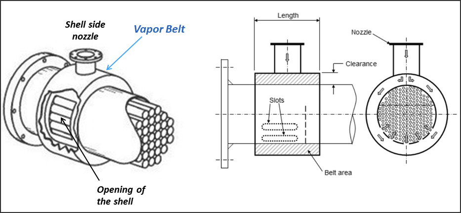
The vapor belt consists of a cylindrical shell, external to the exchanger shell. It replaces the inlet nozzle in both position and function.
This distributor is therefore a chamber subjected to internal pressure, enclosed by a cylinder with a larger diameter than the shell, two lateral closures, and an inlet nozzle that may be equipped with a flange.
Design Mode
The recommended method for calculating these components is to use the "Desktop view" in NextGen, described in this article.
It is possible to use the 3D view, but in this case, it is necessary to create a separate Item.
Adding components
Using the "Desktop view" design mode, you can then proceed by adding:
A cylinder to model the body of the distributor
For the side closures, use the Welded flat cover component, selecting the calculation for a non-circular wall. Insert the circumference of the cylinder above as the largest dimension of the rectangle, and the distance between the exchanger shell and the distributor as the smallest dimension
The "Desktop view" mode supports the calculation of secondary components such as nozzles, once the main component to which they belong has been selected. Then, calculate the inlet nozzle by applying it to the body of the distributor
Finally, you can add the nozzle's flange
These components are generally sufficient to cover the mechanical calculations according to the code. As usual for complex configurations, we recommend consulting with your inspection body to confirm the validity of the approach.
Final considerations
Here are some points the designer may want to keep in mind:
In our experience, an external pressure calculation for the exchanger shell, in the portion covered by the vapor belt, is not necessary. However, if you wish to account for this, it would be appropriate to insert an external pressure value equal to the differential pressure/drop for the exchanger shell only, defining an unsupported length equal to the length of the distributor.
The shell may be weakened by the holes that connect it to the distributor, depending on the configuration. To account for this, the drilling efficiency (ligament efficiency) calculation can be used. Alternatively, if this calculation is not available in the adopted code, the efficiency can be manually calculated and entered in place of the joint efficiency.
Search the documentation
Customer area
Categories
Articles in this category
- Design a body/girth flange automatically using the Flange Designer tool
- How to design an hairpin or double pipe heat exchanger
- How to design a vapor belt for an heat exchanger
- How to design a double tubesheet heat exchanger
- Low temperature design according to AD 2000 code
- Design of adjacent VSR openings beyond 0.8 De of a formed head
- Fatigue Analysis Screening, Method B according to ASME Section VIII div 2 Clause 5.5.2.4
- Using the Usage Factor function to calculate the percentage of component utilization
- PED compliance for equipments designed according to ASME
- Maximum Allowable Working Pressure (MAWP) and hydrostatic test pressure calculation
- Vortex shedding calculation according to EN13445 Clause 22.10
- Clamp connections
- Item revision system
- How to design supports for stacked equipments