Using the Usage Factor function to calculate the percentage of component utilization
Usage Factor is a function present in NextGen for some years, which allows the consultation of a graph representing the percentage of use of the various components. This percentage is calculated as the ratio between a maximum allowable value and an actual value: for example, these values can be the design pressure and the MAWP, or allowable stresses and actual stresses.
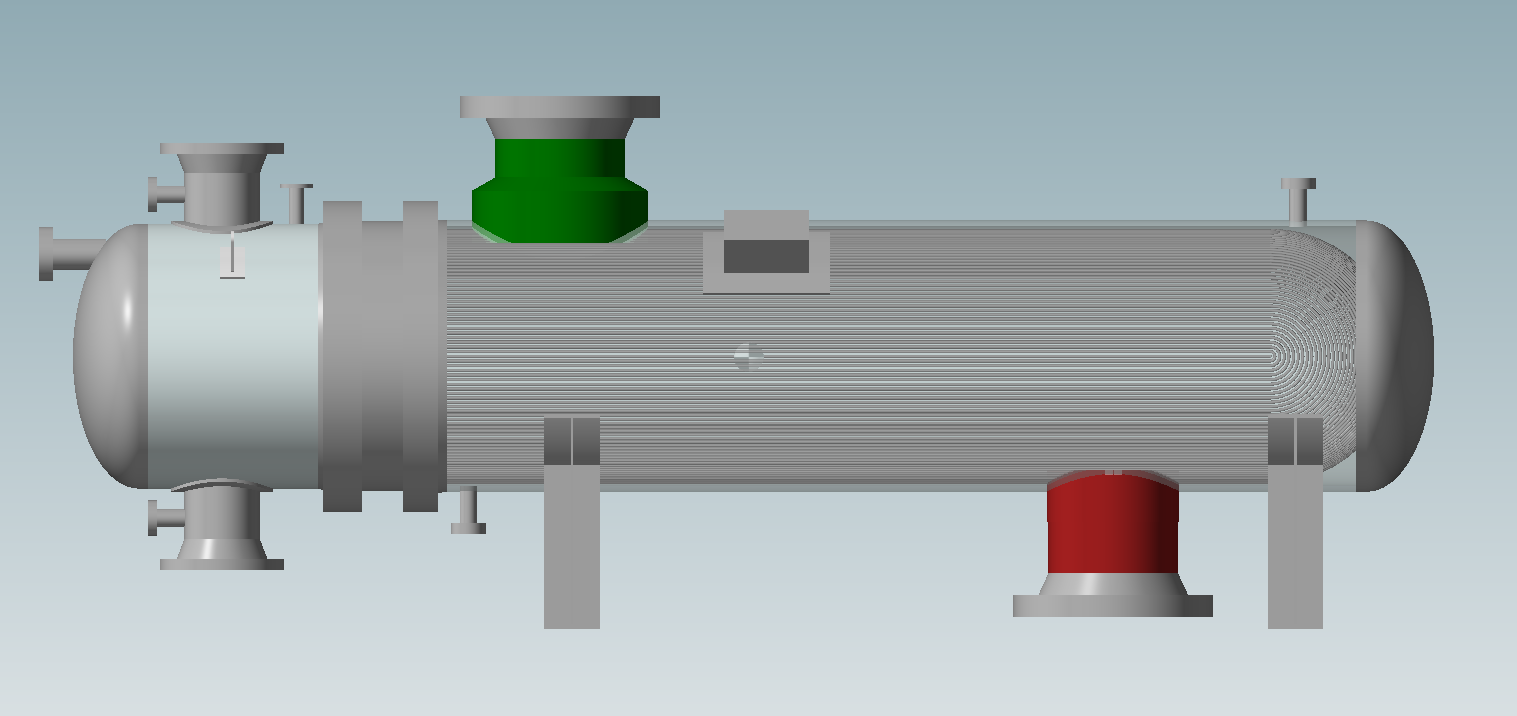
In the example shown in this article we will use a BEU heat exchanger in which there are two nozzles on the shell side, one of which is deliberately not validated.
Usage Factor calculation
The value expressed by Usage Factor adopts the following formula: U=P/Pmax*100
Therefore, based on the context, we will have for example the relationship between internal design pressure and MAWP or MAP, or external design pressure with MAEWP and MAEP.
Usage Factor in the component designer
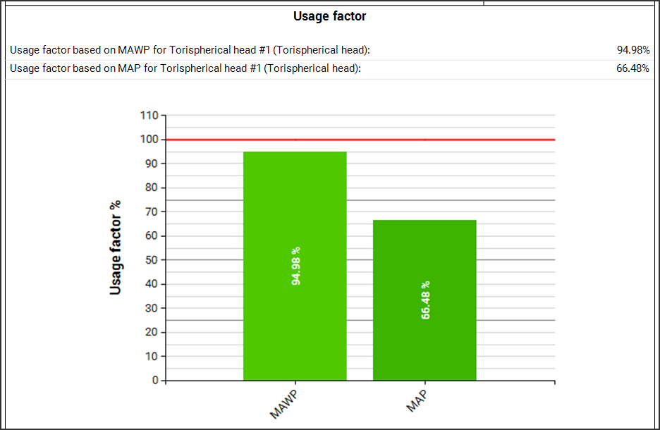
In the component editing window, there is a tab called "Usage Factor": once the input for the component is complete and it is therefore possible to validate it, by accessing this tab the usage graph is displayed.
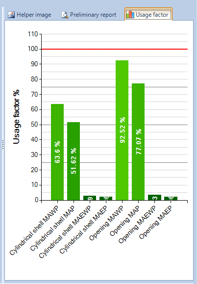
The image above shows the graph for a correctly validated nozzle. You may notice that there are distinct values for:
analysis of the nozzle as a cylinder and as an opening
maximum internal and external pressures
maximum pressures in hot and corroded condition (MAWP) or new and cold (MAP)
Components are valid if their utilization factor is less than 100%, highlighted by the red line. The closer a column of the graph is to the 100% line, the more you are using all the material available on the component.
Of course, the considerations to make vary from component to component and also the graph shown will be contextual to the type of component calculated. In the case of a nozzle, for example, the calculation of the opening compensation will easily determine its stability, over the calculation as cylinder. The designer's goal should be to get close to 100% under internal pressure MAWP conditions, so as not to bring excess material.
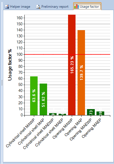
In the second nozzle there are some validation errors. The usage factor of the component exceeds 100% in the calculation of the opening.
The NextGen validation system provides qualitative information on the validation status of a component, whereas the Usage Factor adds quantitative information, helping to identify how much a component is undersized in case of errors but also oversized in case of lack of errors.
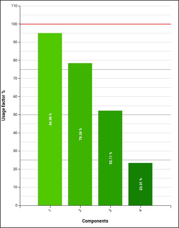
General Usage Factor and comparison between heterogeneous components
Through the icon in the upper toolbar it is possible to open the general window of Usage Factor.
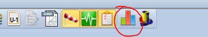
By clicking on the highlighted icon, the following window is displayed:
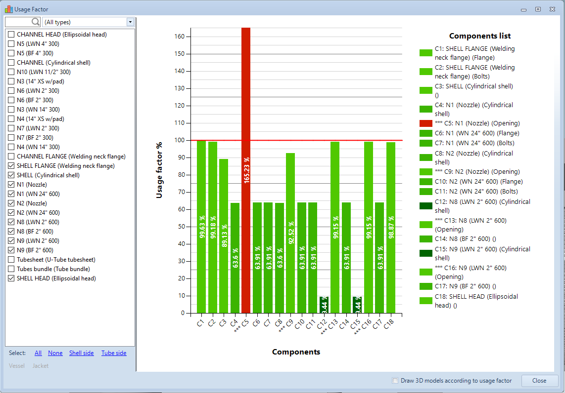
In this screen it is possible to addone or more components of your choice to the analysis. There are buttons for quick selection of components belonging to the same exchanger side or vessel side.
The value displayed in this case is a grouping of all the parameters seen previously, which expresses the worst load case on the component.
The nozzles, being present as cylinders and as openings, are distinguished by a series of asterisks in the case of the calculation as opening
From the graph shown in the example it can be deduced which components are undersized (the nozzle seen above) as well as which are oversized (in this case they are the cylindrical sections of some long welding neck flanges).
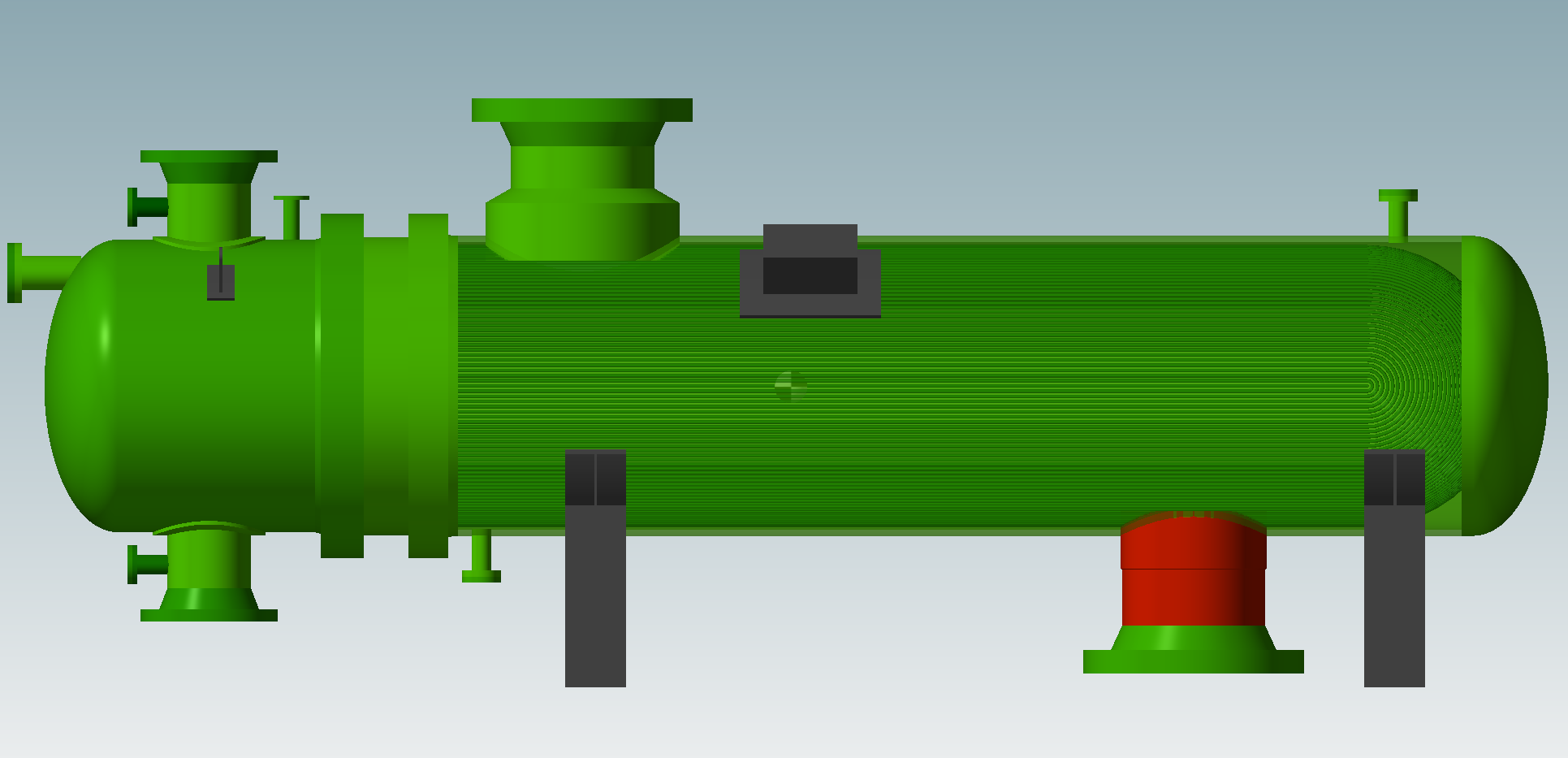
Finally, it is possible to set an option to color the elements of the 3D view according to the utilization factor of each component: different shades of green and red will be used.
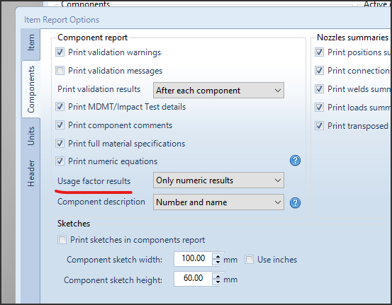
Usage Factor in the Calculation Report
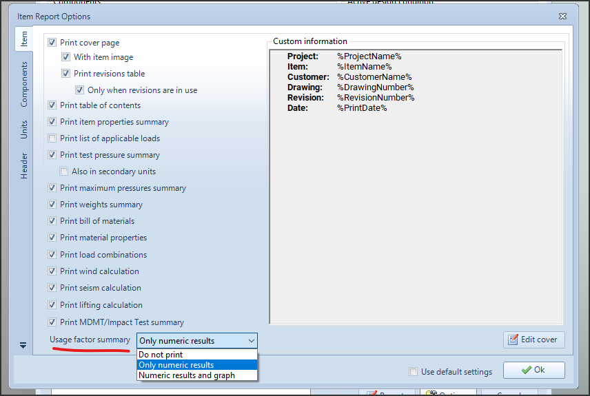
The 2024.0 version of NextGen introduces the possibility of printing Usage Factor values both in summary form and within the reports of the individual components.
Summary
The print options window allows the selection of the summary in tabular, tabular and graphical form or its exclusion from the report:
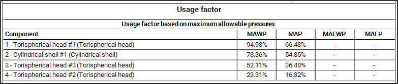
Single component
Similarly, in the Components section it is possible to set the printing of Usage Factor information in the reports of the individual components:
Search the documentation
Customer area
Categories
Articles in this category
- Design a body/girth flange automatically using the Flange Designer tool
- How to design an hairpin or double pipe heat exchanger
- How to design a vapor belt for an heat exchanger
- How to design a double tubesheet heat exchanger
- Low temperature design according to AD 2000 code
- Design of adjacent VSR openings beyond 0.8 De of a formed head
- Fatigue Analysis Screening, Method B according to ASME Section VIII div 2 Clause 5.5.2.4
- Using the Usage Factor function to calculate the percentage of component utilization
- PED compliance for equipments designed according to ASME
- Maximum Allowable Working Pressure (MAWP) and hydrostatic test pressure calculation
- Vortex shedding calculation according to EN13445 Clause 22.10
- Clamp connections
- Item revision system
- How to design supports for stacked equipments