Maximum Allowable Working Pressure (MAWP) and hydrostatic test pressure calculation
By MAWP of a component we mean the maximum pressure which, applied at the highest point of an appliance (where the safety valve is usually positioned), is compatible with the nominal thickness of the component itself.
This pressure, different for each component, depends, as well as on the nominal thickness of the component, also on the hydrostatic head present on the lowest point of the component itself: it is in fact equal to the maximum pressure that the component can bear, decreased by the hydrostatic head which, in operating conditions, is applied to it: this is because the pressure measurement point is always conventionally assumed to be at the highest point of the device.
The MAWP of the appliance will be the lowest value among the MAWPs of the various components.
There are two types of MAWP: the actual MAWP is the so-called "hot & corroded", i.e. the one at design temperature assuming all thicknesses net of corrosion (and tolerance); but there is also a "new & cold" MAWP, i.e. the one at room temperature calculated assuming all thicknesses gross of corrosion (but not of tolerance). The latter has its importance in the calculation of the maximum permissible hydraulic test pressure according to ASME, as will be seen later.
It should be noted that the hydrostatic head in operating conditions is almost always lower than that under test: this is because in operation the level of the liquid inside is generally lower than the total height of the appliance (at most it may not even be there a liquid level), while during testing the appliance is always completely full of water; and because the density of the liquid is generally lower than that of water (pressure due to the head in MPa = liquid density in kg/m3 x 9.81 m/s2 x height in m)
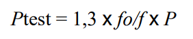
The calculation formulas, the allowable stresses and the formula for calculating the test pressure are always designed in such a way that, assuming the hydrostatic head is negligible both in operating conditions and in test conditions, the hydraulic test cannot result in a required thickness greater than the one required for the design: in particular, both in ASME VIII division 2 and in EN 13445 the following situation occurs:
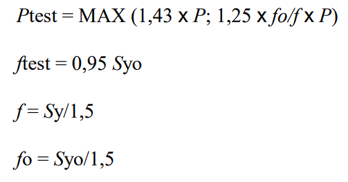
where P for EN 13445 is the design pressure, while for ASME VIII Division 2 it can be both the design pressure and the MAWP since the minimum calculation thickness of a cylinder is given by a
formula like this:
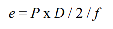
In design conditions we have:
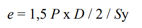
while in test conditions one of the following two situations can occur:
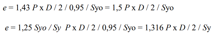
Comparing these two formulas with that of the e in design conditions, in the first case the e of the test is lower because the elastic limit at room temperature is always higher than the elastic limit at design temperature, in the second case because 1.316 < 1.5. All this under the assumption that corrosion is zero; if, however, the corrosion has a finite value, even more so the minimum thickness calculated in the design is also adequate in the test, given that in the test the thickness must always be considered gross of the corrosion.
All this continues to be true even if P is replaced by the "hot & corroded" MAWP, because, by the definition itself, the "hot & corroded" MAWP is the one that generates a minimum thickness equal to the nominal thickness.
However, the same is also valid for ASME VIII division 1, in which the test pressure is:
In fact, considering that in ASME VIII division 1 an allowable value in test conditions of 0.9 Syo is prescribed, following all the steps the e of the test would in fact result:

However, things change if the hydrostatic head is sensitive, and if the one being tested is very different from the one in design: in fact, called HD and HT are the pressures corresponding to the hydrostatic heads in design and in test respectively, instead of P in the design formula it is necessary to introduce P + HD, while in the test formula it is necessary to introduce Ptest + HT; it is evident that with very high HT values (in the case of columns) the hydraulic test can be significant.
ASME VIII, both in division 1 and in division 2, suggest a method to avoid a direct verification of the thicknesses in hydraulic tests, which can be used in all cases in which the checks are not done using formulas that presuppose the comparison between a effective stress and an allowable stress, different between design and test, as in the case of the cylinder described above. In external pressure tests, for example, the comparison is made between a maximum allowable pressure and the actual design pressure, but no prescription is given for carrying out a similar test calculation. In all these cases, the procedure described below must be followed, based on the calculation of the "basis for calculated test pressure".
Calculate, for each component of the appliance, the “new & cold” MAWP
Add to this value the relevant hydrostatic head in design and subtract the value of the relevant hydrostatic head in test conditions: this way, the MAWP of the appliance is obtained which would be acceptable for a given component at room temperature, in non-corrosive conditions and with a hypothetical hydrostatic head equal to the one existing in test.
The lowest value among all the pressures calculated in this way is the “basis for calculated test pressure”.
The maximum allowable hydraulic test pressure is the one obtained by calculating the test pressure starting from the "basis for calculated test pressure" with the rules established by the reference code, taking into account that this time it is a design pressure at room temperature; therefore the maximum test pressure for ASME VIII division 1 will be 1.3 times the "basis", while for ASME VIII Division 2 will be 1.43 times the "basis".
If the test pressure thus obtained is higher than expected, there is no need to make further test calculations; if it is lower, it will be necessary to increase the thicknesses of those
components that contribute most to lowering the "base" (i.e. those for which the hydrostatic head is higher).
In practice this method allows a verification in test conditions to be traced back to an equivalent verification in design conditions, carried out at room temperature and in non-corrosive conditions. If the verification must then be made explicit, a "basis" is calculated starting from the test pressure and a design check is carried out assuming the "basis" as the design pressure, adding to this, in the calculation of each component, the hydrostatic head scheduled for the test.
Search the documentation
Customer area
Categories
Articles in this category
- Design a body/girth flange automatically using the Flange Designer tool
- How to design an hairpin or double pipe heat exchanger
- How to design a vapor belt for an heat exchanger
- How to design a double tubesheet heat exchanger
- Low temperature design according to AD 2000 code
- Design of adjacent VSR openings beyond 0.8 De of a formed head
- Fatigue Analysis Screening, Method B according to ASME Section VIII div 2 Clause 5.5.2.4
- Using the Usage Factor function to calculate the percentage of component utilization
- PED compliance for equipments designed according to ASME
- Maximum Allowable Working Pressure (MAWP) and hydrostatic test pressure calculation
- Vortex shedding calculation according to EN13445 Clause 22.10
- Clamp connections
- Item revision system
- How to design supports for stacked equipments