How to create a jacketed vessel
These are the steps required to to enable a jacketed vessels calculation.
At the end of the article you can find the indications on how to force the calculation with the external pressure of a component and its related hydraulic test, as if it is surrounded by a jacket.
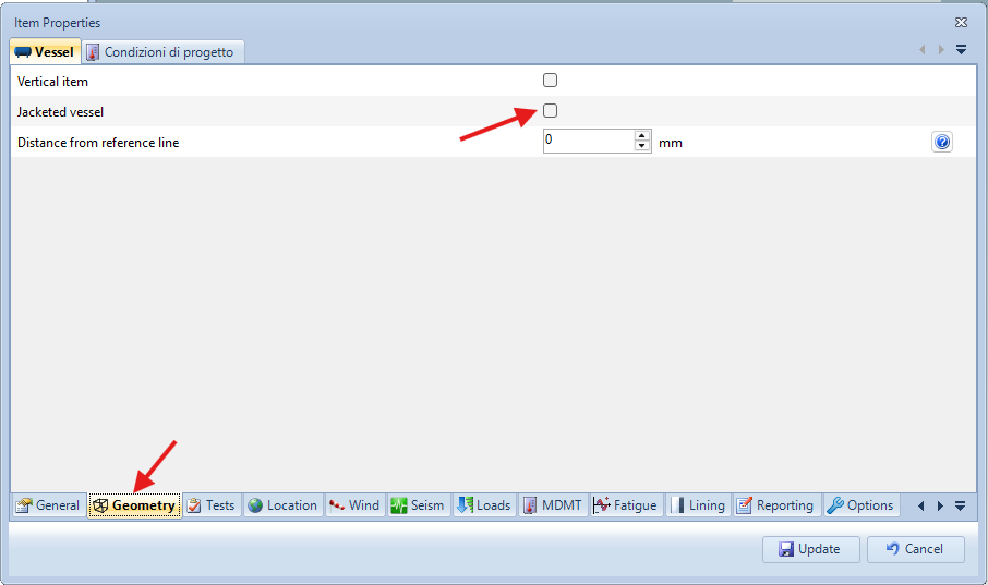
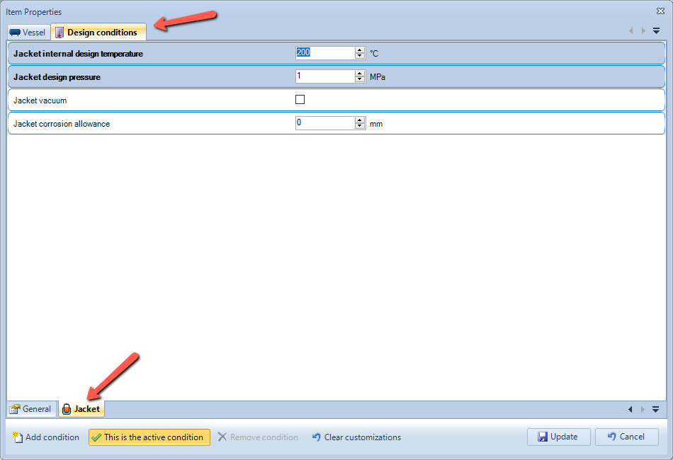
Enable "Jacketed vessel option" under Item > Properties > Geometry tab. Define jacket conditions in the same window by switching to Operating conditions tab, then Jacket. The software will automatically take into account the effects of the pressure of the jacket in relation to the vessel underneath and vice versa:
Design the vessel as you would normally do
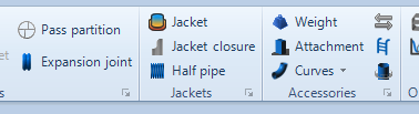
When main shell - the one where jacket shall be applied to - is selected, "Jacket" icon in the main toolbar is enabled:
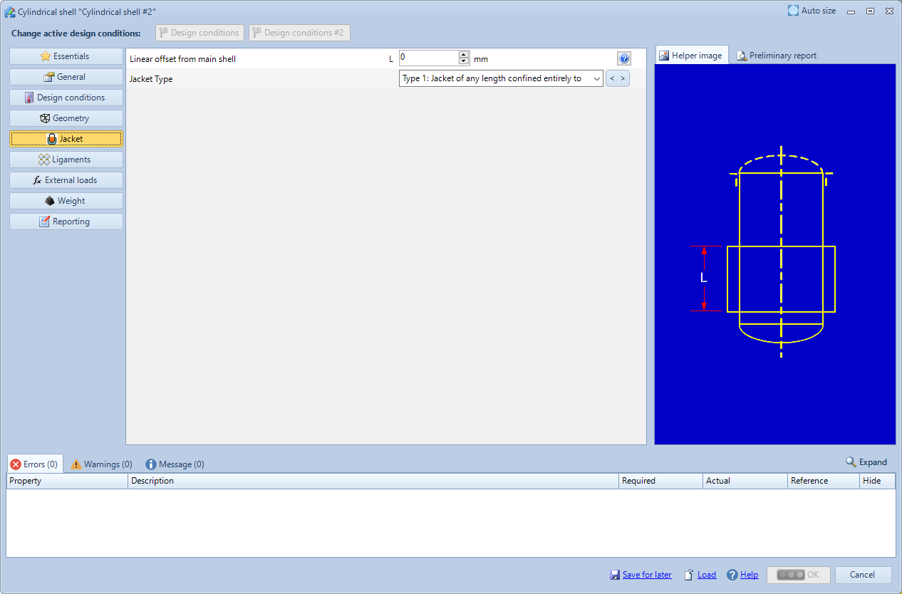
By clicking on "Jacket" icon the external cylinder of jacket is added. Fill in dimensions, material and set its L offset from the base of previously selected (point 3) main shell:
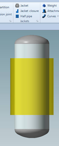
The jacket will be placed around main shell:
From now on it is possible to connect other elements constituting the whole jacket, e.g. heads, cones and closures.
The software will automatically perform the external pressure calculation on the underlying members. It is recommended to manually check and set the unsupported length actually subjected to stress on these components, since the software automatically conservatively considers the entire length of the component.
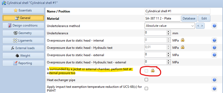
Consider a component as surrounded by a jacket
After completing the point 1. of the previous guide, you can force the
calculation with external pressure and its related hydrostatic test of a component by unlocking the following property and ticking the checkbox.
Search the documentation
Customer area
Categories
Articles in this category
- How to create a reinforced ring opening (studding outlet flange)
- How to create a jacketed vessel
- How to use a National Annex in EN1991-1-4
- Forming Strains in ASME
- Set liquid level
- Limits on thickness for tubes and cylindrical shells in the VSR standard
- Thread calculation according to EN14359 Clause 5.5.6
- Cladding and weld overlay management
- How to design a stiffening ring against external pressure using NextGen
- Standard flanges and flanges according to calculation code
- Common mistakes when searching EN 1092-1 flange ratings
- Definition of standard tees in EN 13480
- How to design a gas cylinder with NextGen