How to design a stiffening ring for external pressure with NextGen
Stiffening rings, or stiffener rings, are elements placed outside or inside a shell to make a vessel more resistant to external pressure. In particular, the rings are considered "effective reinforcements" and therefore contribute to shortening the "maximum unsupported length", which is the greatest length of the vessel without any element considered effective against buckling (body flanges, rings, bottoms).
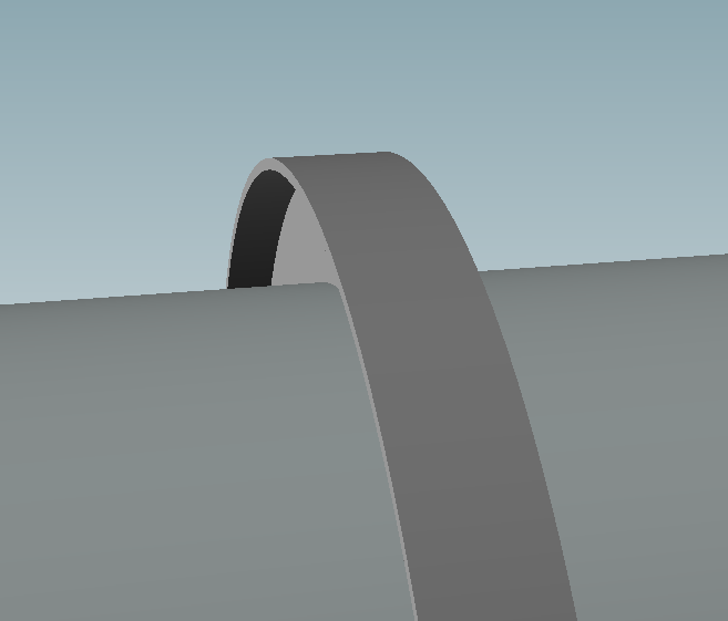
Remember that the system generally used by calculation codes provides for the verification of the ring by evaluating its moment of inertia with respect to a required moment. To maximize this value it is necessary to bring as much area as possible in a section far from the reference axis (the surface of the shell). Modest values of required moment of inertia can be compensated with a vertical plate, in case of higher required values it is necessary to add a horizontal flange to this plate.
Component selection and setting
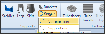
The addition of rings is available for cylindrical and conical shells. After selecting the component to which you want to apply the ring, choose from the ribbon Rings > Stiffener ring
In the component design window, in addition to the usual material selection, you can choose the ring configuration:
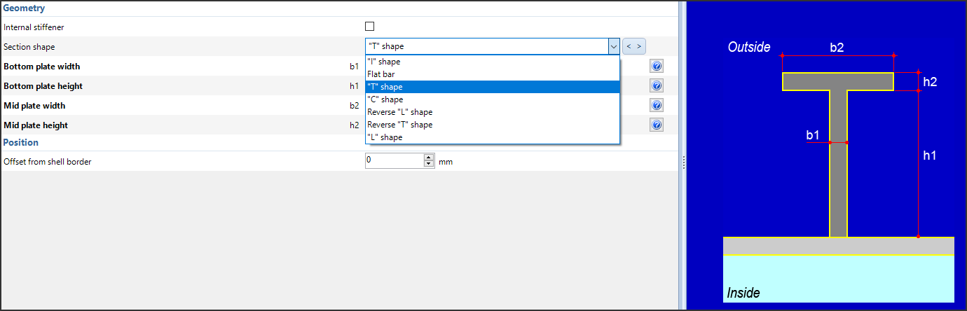
For the various available configurations, NextGen shows a preview image of the section. Once the shape has been set, enter the dimensions of the rectangles that make up the chosen section.
The positioning of the component, as in all the other secondary elements in NextGen, is based on the distance from the reference (in this case the left or bottom edge of the shell, depending on its orientation).
Peculiarities of different calculation codes
Each calculation code available in NextGen adopts a different method for checking rings: it is necessary to refer to the code in question to evaluate the different options.
For example, the EN 13445 code distinguishes between "light" and "heavy" stiffener, in Chapter 8; this distinction has a different effect on the calculation of the maximum unsupported length.
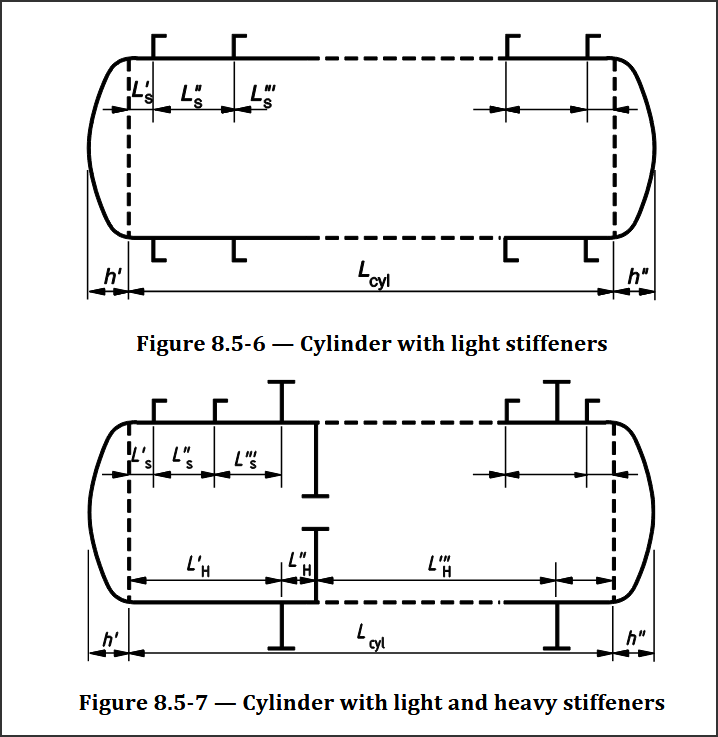
Various rings configurations in EN 13445-3
For the ASME VIII Div. 1 code, there is an option to calculate the moment of inertia by combining the ring section with the shell section. If you enable this option, make sure to define the welds in the Welds category.
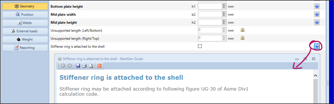
Combined moment of inertia calculation in ASME VIII Div. 1
Finally, the availability of the calculation of internal rings can also be influenced by the context.
Validation of rings and shells
The use of a ring involves, unlike most components, a double validation:
The ring is verified at external pressure, usually by comparing a required moment of inertia with an available moment of inertia as defined in the Calculation Code
In addition, a ring involves the modification of the maximum length not supported in the calculation at external pressure of the component to which it is connected.
When the component is first defined, only the first of the two validations described above is performed, since the component has not yet been added to the model and its parent component cannot yet "feel" it. To validate the cylinder or cone, simply confirm the addition of the ring, then re-validate by reopening its edit tab.
Search the documentation
Customer area
Categories
Articles in this category
- How to create a reinforced ring opening (studding outlet flange)
- How to create a jacketed vessel
- How to use a National Annex in EN1991-1-4
- Forming Strains in ASME
- Set liquid level
- Limits on thickness for tubes and cylindrical shells in the VSR standard
- Thread calculation according to EN14359 Clause 5.5.6
- Cladding and weld overlay management
- How to design a stiffening ring against external pressure using NextGen
- Standard flanges and flanges according to calculation code
- Common mistakes when searching EN 1092-1 flange ratings
- Definition of standard tees in EN 13480
- How to design a gas cylinder with NextGen