How to create a reinforced ring opening (studding outlet flange)
In this article we're referring to the calculation of those openings in shells reinforced by an usually forged, thick nozzle having holes to connect a blind flange. These outlets have different names in different calculation codes: EN 13445 refers to them as reinforced ring, ASME as studding outlet type flange while they're called reinforcing pad in PD 5500.
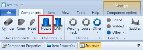
The insertion of a studding outlet takes place from the same command you use to add a nozzle to your vessel:
From the component design window, it is then necessary to select the correct type of nozzle:
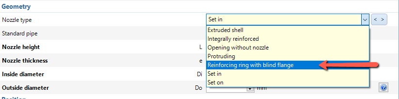
Not all calculation codes have specific rules for this type of attachment. If the code in use does not contain the item Reinforcing ring with blind flange (see for example the note at the bottom of this page regarding ASME codes), it is possible to choose the connection type Set in or Set on, depending on whether the nozzle penetrates or is resting on the shell.
It is then necessary to enable an additional option that allows:
to connect a blind flange in the 3D model
to take into account the smaller area of the section when calculating the compensation
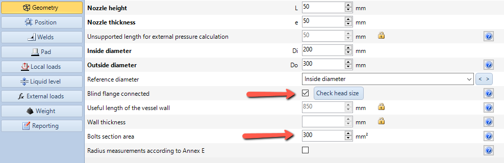
In the "Geometry" category, select "Blind flange connected". Using the "Check head size" button it is also possible to size the nozzle on the basis of the dimensions of the blind flange that will be connected.
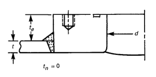
In the "Bolt section area" enter the section area of two bolt holes:
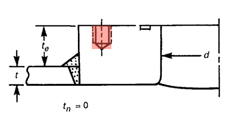
This area does not contribute to the reinforcement of the opening and will be subtracted during the calculation. The value to be inserted equals two times the depth of the hole times its diameter, since in the worst case the section under analysis includes two bolt holes.
A note for ASME calculation
As the BPVC does not have an explicit support for such configuration, the nozzle must be treated as a simple set-in connection. When a blind flange is then connected to the studding outlet, validation of tapped bolt holes according to UG-43(g) is automatically performed.
Search the documentation
Customer area
Categories
Articles in this category
- How to create a reinforced ring opening (studding outlet flange)
- How to create a jacketed vessel
- How to use a National Annex in EN1991-1-4
- Forming Strains in ASME
- Set liquid level
- Limits on thickness for tubes and cylindrical shells in the VSR standard
- Thread calculation according to EN14359 Clause 5.5.6
- Cladding and weld overlay management
- How to design a stiffening ring against external pressure using NextGen
- Standard flanges and flanges according to calculation code
- Common mistakes when searching EN 1092-1 flange ratings
- Definition of standard tees in EN 13480
- How to design a gas cylinder with NextGen