How to validate an attachment (nozzle or support) according to WRC 107, WRC 537 o WRC 297
NextGen can calculate stresses in shell and, in some cases, stresses in nozzle at the junction with shell according to WRC bulletins (Welding Research Council) 107, 537 e 297.
Applicability
Bulletin WRC 107 contains directions to calculate local stresses in cylindrical and spherical shells due to external actions. Bulletin provides a series of chars to calculate needed parameters to compute stresses; since this system doesn't work very well with modern electronic calculators, Welding Research Council recently published an update, named WRC bulletin 537, which contains the same charts in equation format. Bulletins are therefore equivalent: WRC states that bulletin 537 is a reprint of bulletin 107, not an update ("It is not un update or a revision of 107. It is the 2010 printing of WRC 107").
Supplementary bulletin WRC 297 contains directions to calculate local stresses in nozzle too, other than those in shell. The applicability is limited to nozzles on cylindrical shells.
Attachment type
As stated in bulletins, NextGen supports the following configurations:
On a cylindrical shell, WRC 107/537 e WRC 297:
Hollow cylindrical attachment (nozzle)
Rigid cylindrical
Rigid rectangular
On a spherical shell, solo WRC 107/537:
Hollow cylindrical attachment (nozzle)
Rigid cylindrical
Hollow squared
Rigid squared
How to calculate WRC values with Sant'Ambrogio NextGen
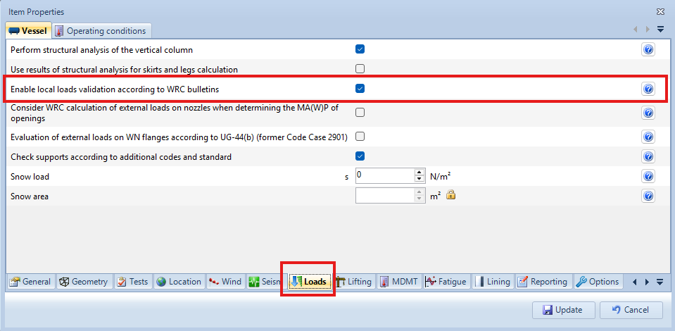
First step needed is to enable WRC under File > Item Properties. Select Loads tab, then enable the appropriate check box.
Now, every nozzle, LWN or rigid attachment added to the item contains a new WRC tab. Open the nozzle you want to validate and select the WRC tab like shown in figure.
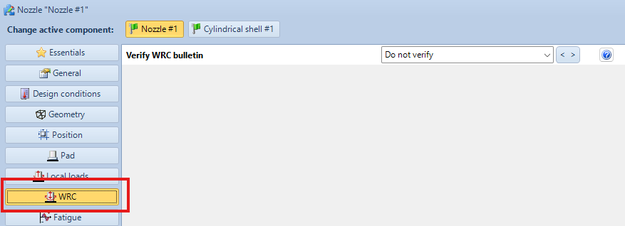
From the drop down menu "Verify WRC bulletin" it's possibile to enable one or more bulletins to be used in validation. As an option, WRC 107 can be selected instead of 537.
Once WRC is enabled, two more controls will be shown:
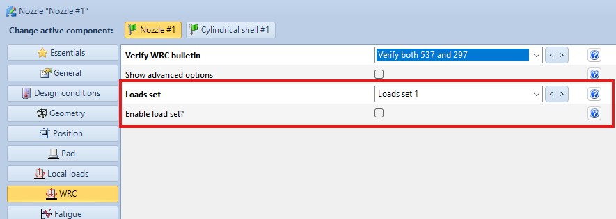
For every component, a maximum of 5 "loading cases" can be calculated. Each loading case is a combination of stresses acting alone on the nozzle. To select a loading case (or load set), use the appropriate drop down menu. To enable it, use the checkbox; a load set can be kept disabled, all data are retained but it's not validated neither printed.
After enabling a load set, some input controls are shown, some options are visible after selecting the control "Show advanced options":
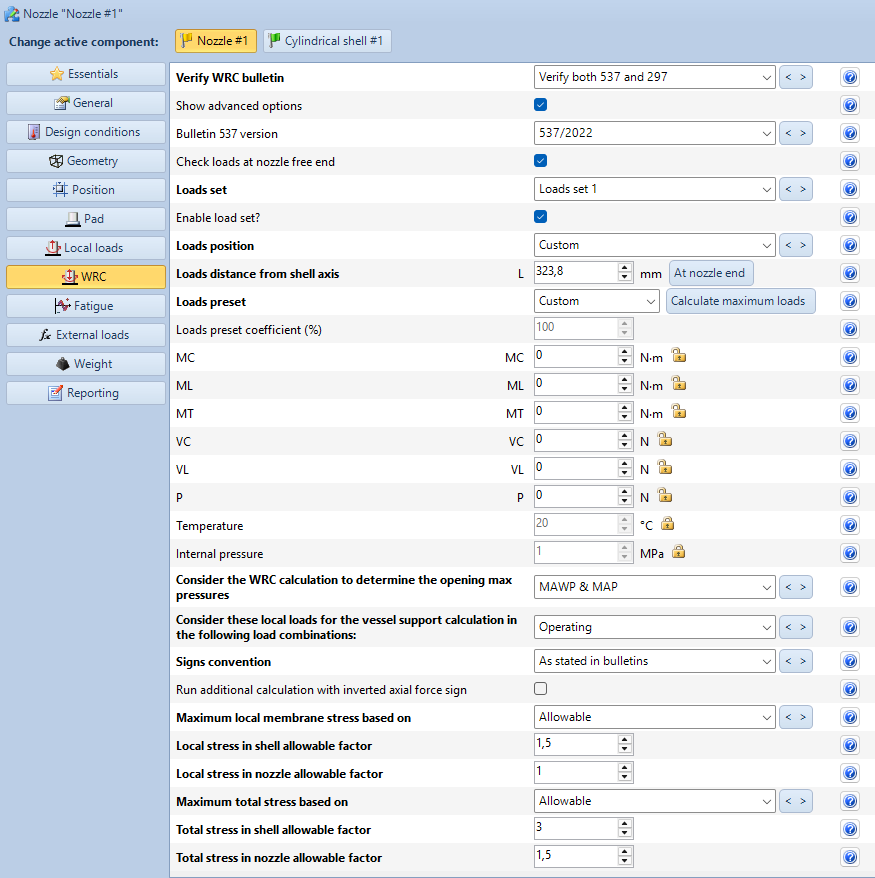
From top to bottom, available inputs are:
Internal temperature and pressure: WRC is normally validated with design data; to use different T and/or P, unlock the padlock icon and type in the new values
Loads position: by using this drop-down menu the position where loads are applied can be chosen. If a custom position is chosen, a new input box allowing to input the distance from shell axis (on a cylinder) or outside diameter (on a spherical shell) is shown
Signs convention: bulletins 107/537 and 297 use two different sign conventions to indicate forces and moments directions. With this menu sign conventions can be uniformed: this feature is useful in case results need to be compared to those obtained with to Sant'Ambrogio "Special" software, which uses 297 signs also for 107.
Run additional calculation with inverted axial forces signs: enable this option to run an additional calculation with inverted axial forces signs
Local membrane stress factor e total stress factor: coefficients applied to allowable membrane stresses and total allowable stresses
Loads preset: by using this menu it is possible to change the loads values between a "custom" set (input is left to the user) or a percentage of Saipem/Snam loads based on Snamprogetti STD-CR-GEN-7058 specification. By pressing the "Calulate maximum loads" button it is also possible to let the program increase the stresses, on a 1:1000 ratio between forces and moments, until the component stays validated. This is useful as a boilerplate, a fine-tuning of loads may be required.
MC, ML, MT: in these fields it is possible to input values for circumferential, longitudinal and twisting moments acting con attachment. When an attachment is placed on a spherical shell, MC and ML are replaced by M1 and M2, since a sphere doesn't have a circumferential or longitudinal direction
VL, VC, P: in these fields it is possible to input values of forces acting in circumferential, longitudinal and axial direction. As said for moments, forces VL and VC are replaced by V1 and V2 on spherical components.
Validation runs as usual once every required field is filled.
Calculation on supports
When WRC needs to be used to calculate the stresses transmitted from a support like a leg or bracket, the same procedure applies. In those cases, a button is displayed, useful to copy applicable loads (notably, vertical loads) transmitted from support to shell.
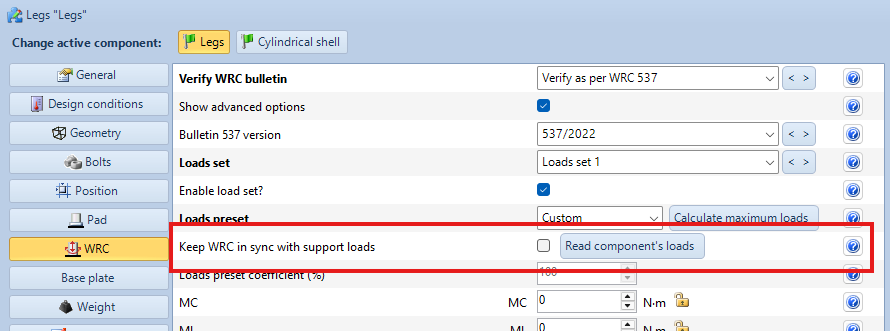
After using this function, user needs to check values and modify them to consider any eventual other stress not inferable by support calculation.
Report
WRC section is added to the component's report (e.g., nozzle), following normal pressure validation according to current calculation code.
Search the documentation
Customer area
Categories
Articles in this category
- Weight management
- Wind load definition
- External actions for the vessel support calculation
- Period of vibration of items supported by brackets or rings
- Run a FEM analysis of a nozzle with NozzlePRO from NextGen
- How to validate an attachment (nozzle or support) according to WRC 107, WRC 537 o WRC 297
- Version 2019.3, WRC module updates
- Use of customized Excel files to define the WRC loads on nozzles
- Local loads transformation
- Simplified fatigue assessment according to EN13445-3 Clause 17 and AD 2000 S 1
- Detailed fatigue assessment according to EN 13445-3 Clause 18 and AD 2000 S 2
- Erection of vertical vessels
- Updates to simplified fatigue assessment in Clause 17 according to EN 13445-3 2014, Amendment 5
- Considerations on the verification of saddles according to the Zick method
- ASME Code Case 2901, Division 1 UG-44(b) and Division 2 4.16.12
- Bolt torque calculation for flanges
- Structural calculation of supports using load combinations
- Calculation of foundation loads for saddle-supported vessels using simplified finite element analysis