Getting started step-by-step guide
What is NextGen?
NextGen is a mechanical, multi-code calculation software aimed to design pressure vessels and heat exchangers. The design can be performed according to these standards: ASME VIII Division 1, ASME VIII Division 2, EN 13445, AD2000, VSR.
The software is able to validate structural analysis of supports according to different codes and de-facto standards like NTC, WRC, UBC, ASCE, Moss, Bednar, etc.
Installing the software
You can find a guide about installation and license management in this article.
Prerequisites
This guide assumes that the software is correctly installed and working. It is also assumed that the end user has a basic understanding of pressure vessels design criteria and knowledge of current calculation codes.
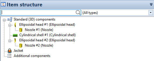
Project Browser
The first window shown after program startup is the so-called "Project Browser". The Project Browser gives an overview of the user's projects and can operate on them. The default location of the user's projects is Documents\Sant'Ambrogio Projects.
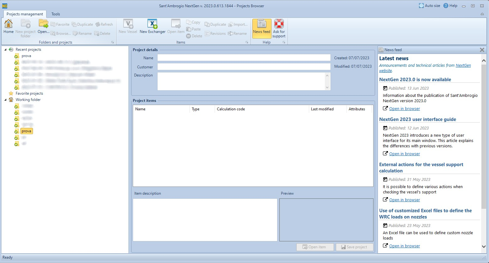
Project Browser
Project and Item definitions
A NextGen Project (.SPJ file extension) is a container that includes references to one or more Items (.SIT file extension). An item includes multiple components and represents a vessel or an heat exchanger; it contains all the required data (geometry, loads and so on) to validate them. The user can take advantage of this hierarchy at his own will; usually, a project maps to an order.
For our "Classic Edition" software users, a single .SIT Item file contains all the components previously designed on different .IN input files.
Project Browser features
The main Project Browser's functions can be found on top of the window:
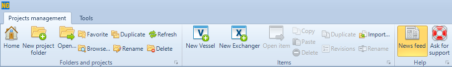
Main Project Browser's features
The functions present in the "Folders and projects" section allow the user to perform common operations like creating, opening, deleting or renaming a project.
The functions present in the "Item" section allow the user to create and open items (vessels or heat exchangers) and also perform common operations on items such as copying, deleting and renaming. For items, also importing is possible.
A detailed explanation about how to import an item into a project can be found in this article.
The "Help" section contains two buttons, one for showing the news feed and one for sending technical support requests to our support team.
More information on the technical support functionality can be found in this article.
More information on files management with the Projects Browser can be found in this article.
The "Tools" tab of the ribbon bar contain other functions which are useful for unlocking or making an item read-only, as well as the possibility to access the software options and the materials database. It is also possible to show the installed calculation codes, check for updates, show license details and locate the program's log (useful for diagnostic purposes).
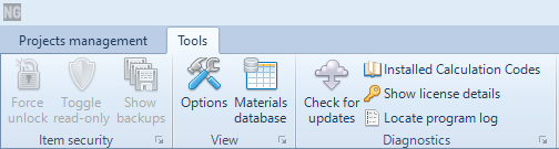
"Tools" tab
Creating a new project
From the "Projects management" tab, select "New project folder":

"New project folder" button
Write the name of this project into the appropriate field, then click on "Ok" to save it.
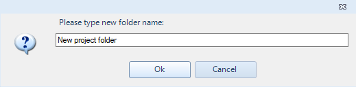
Typing a folder name
At this point, project details such as Customer and Description can be filled. Save the project for saving the modifications, by clicking on the "Save Project" button.
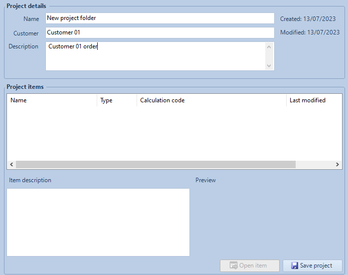
Filling project details
The "New Vessel" and the "New Exchanger" buttons are now enabled. In this guide we're going to create a simple tank, so click on the "New Vessel" button.
The "Item Properties" window will appear:
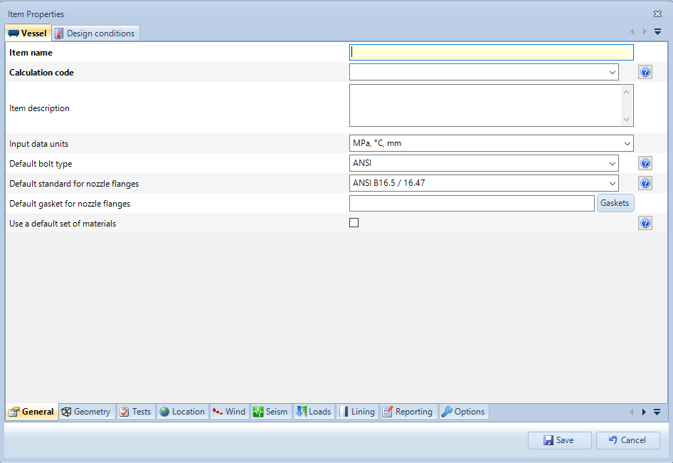
"Item Properties" window
To proceed with a new Item creation it is mandatory to fill each field marked with a bold label. You can always recall the Item properties window later and fill or change any information about the current item. Note that all item properties are grouped by category (general, geometry, tests, etc.): switch between categories by clicking on the appropriate tab. Some tabs may be hidden, click on the arrow to show more tabs.
Fill with the item name (let's call this vessel "New item") and select the desired calculation code, like "EN 13445 Ed. 2021 Issue 1 (2021-04)". The window will refresh to load additional, code-specific fields.
Switch to "Design conditions" by clicking on the top tab to define design conditions for this item:
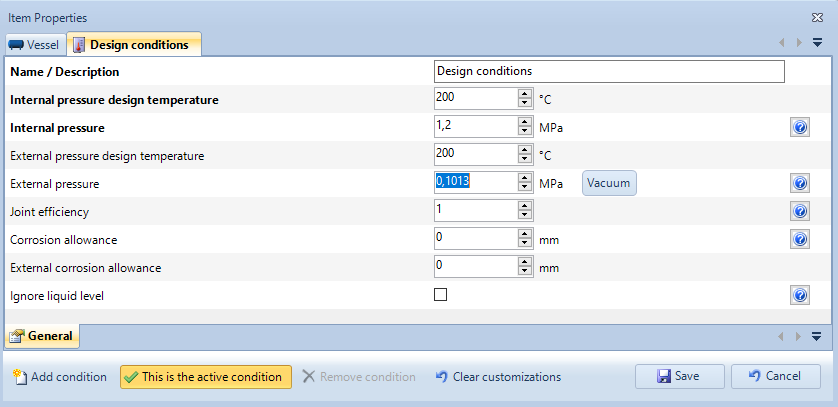
Design conditions
Set temperature and pressure for internal pressure calculation (e.g. 200°C and 1.2 MPa) and, if needed, external pressure conditions (e.g., 200°C and 0.1013 MPa by clicking on the "Vacuum" button). When external pressure calculation is not needed, leave 0 (zero) in the "External pressure" field.
It is also possibile to define a default joint efficiency value and corrosion allowances: these values will be applied on every new component added later. It will always be possible to change them globally or on a per-component basis.
Once finished, click "Save" to begin working on the new item. The main program window will be shown.
Workspace
NextGen contains a ribbon bar organized in different tabs. Using the tabs it is possible to choose the macro-area of the desired command. These macro-areas, or categories, are:
File, for managing saving, opening, revisions, properties related to the current file
Components, for inserting and printing components
Item, for managing properties relating to the entire current item
View, to change the current view and view databases of standard materials and components
Tools, for accessing tools such as software options, export, quick replacement of materials and gaskets
Help, for help and diagnostic functions

NextGen's ribbon bar
From the "Components" tab we can add one of the supported components, like cylinders, cones, heads etc. Some buttons are greyed since in the current context the component can't be added: for instance, a nozzle can't be added to an empty model, since it needs a shell to be placed onto.
Components that can't be added due to license restrictions are shown in red.
In this tab, also the buttons for creating the item's report and the current component's report are available.
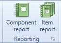
"Component report" and "Item report" buttons
When a component is selected, an additional category, contextual to that component, appears on the ribbon.
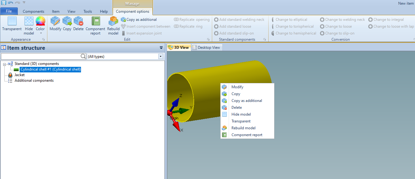
The contextual menu and toolbar
Through these commands it is possible to interact with the component itself, modifying its appearance or carrying out operations such as the conversion, replication or insertion of intermediate components.
The same operations are available by clicking with the right mouse button on the component itself or its icon in the hierarchical tree view.
In the "Item" tab, the user can perform several functions such as accessing the "Item Properties", changing the calculation code, changing the item's orientation, enabling a jacket, defining a liquid level, defining wind and seism loads, defining load combinations.
More information on load combinations can be found in this article.
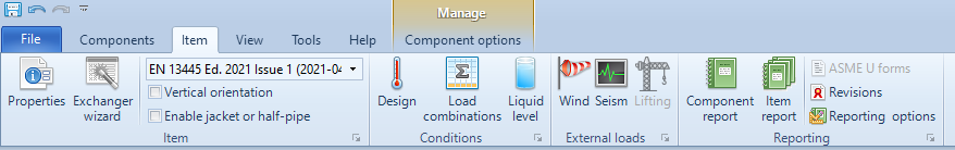
"Item" tab of the ribbon bar
Under the ribbon bar a control for switching between "3D View" and "Desktop View" is present.
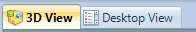
"3D View" and "Desktop View"
The "3D View" gives the user the possibility to create components that will be part of the 3D model, while the "Desktop View" gives the user the possibility create additional components, not represented with a 3D model. An example of creating an additional component is provided in this article.
Left panels can show different information:
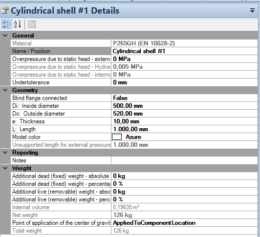
Left panels
A hierarchical view of the item shows validation status (green for validated component, yellow for validated with warnings, red for not validated) for each component and lets the user search within all components; the two remaining panels display the item's or currently selected component's properties; these properties can also be modified rapidly from here.
Finally, the rightmost vertical toolbar lets the user navigate the 3D model and change 3D visualization options.

Right toolbar
Vessel design
Design starts from the main component, usually a cylindrical shell. Select "Cylinder" from the "Components" tab of the ribbon bar and its editing window will appear:
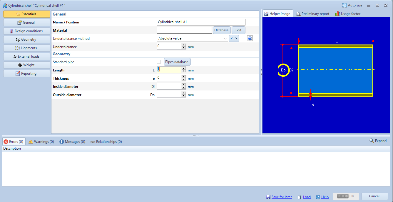
Editing window for cylinders
Tip: The "OK" button is disabled, since not every mandatory field is filled; like in "Item properties", also in this window mandatory fields are highlighted in bold. Hovering the "OK" button with mouse pointer highlights mandatory fields in bright red and moves to the first mandatory field not yet filled: this technique can be used to be guided through the whole input process.
To define a cylinder the only required values are material under "General" and length, diameter and thickness under "Geometry".
To select a material, click on the "Database" button beside the material input text box: the material database of current calculation code will show up.
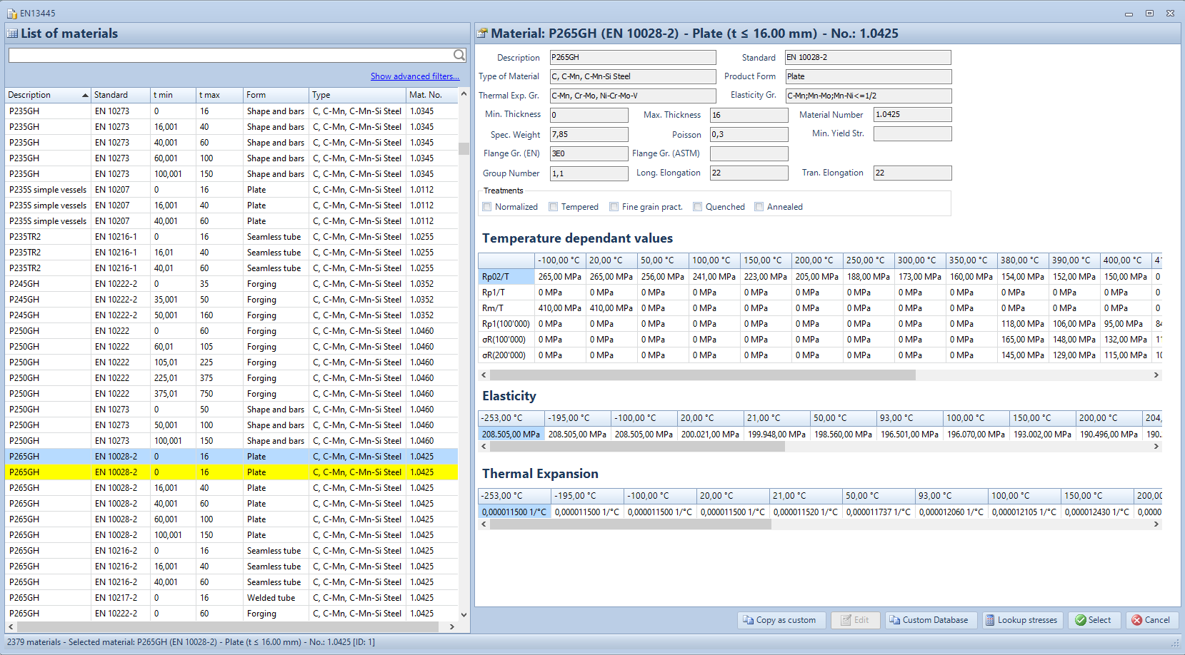
Materials' database
Materials' database can be different from one calculation code to another: in this example, materials are those suitable for EN13445.
Materials highlighted in yellow are "Custom", created by the user. A step-by-step guide to create custom materials is available in this article:
The left panel in the Materials Database window shows the list of all available materials: this list can be sorted by clicking column headers or filtered using the options that appear after clicking on "Show advanced filters":
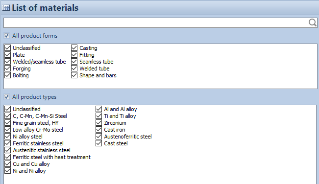
Advanced filters
Type "265" in the search box to find matching materials:
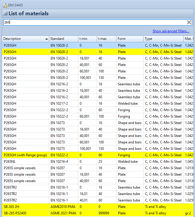
Searching materials
From the now filtered grid, select "P265GH" (tmin = 0, tmax = 16) by double-clicking on it.
Under "Geometry", set cylinder dimensions:
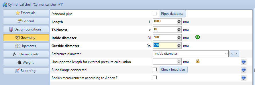
"Geometry" tab
Set length to 1000 mm, thickness to 10 mm and inside diameter to 500 mm. Outside diameter is automatically calculated.
After filling the last required field, the component is automatically validated. Validation is in real time: this means that every time a value is changed, validation is re-run. Validation status is visible at-a-glance on the semaphore icon:
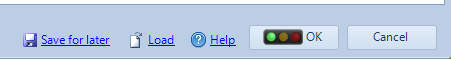
"OK" validation button
A green light means that the current component is fully validated without any issue. A yellow light means that there are warnings about the validation: keep in mind that the warnings don't change the fact that -- according to the current calculation code -- the component is still valid. The designer should take a look at warnings and keep them in mind. A red light means that there are validation errors that must be checked and fixed.
Solving errors
This article contains detailed information about error messages issued by the program and how to handle them.
When NextGen shows a number of errors keep in mind that they should be solved starting from the top of the list: often, following errors are a consequence of preceding ones and they get solved at the same time.
For example, the following images shows an insufficent thickness at internal pressure:
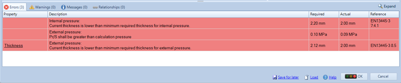
Validation errors
NextGen suggests to increase nominal thicknes to 2.20 mm instead of the current value of 2 mm. Once the thickness is increased over the minimum required value, the following errors also get fixed. In this case, all errors would be fixed since minimum required thickness at external pressure would be satisfied too.
Solving warnings
This article contains detailed information about warning messages issued by the program and how to handle them.
As stated before, warnings are different from errors: they don't have to be seen as something to get rid of to have a valid calculation. A calculation without errors that contains warnings is perfectly acceptable. When the calculation report is printed, warnings can be omitted (while errors can't): they are shown to help the user in getting the best design possible.
Some warnings can be easily removed by following what's written in them. For example, when a small opening is placed on an ASME VIII Div. 1 shell, the following message is shown:
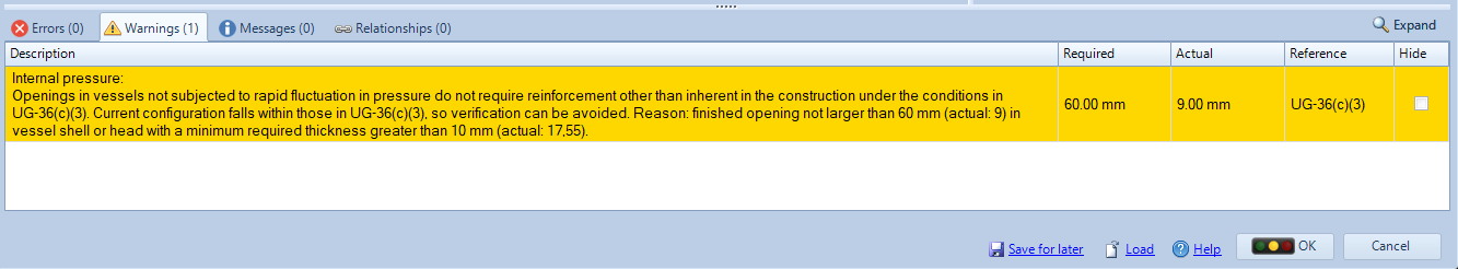
Validation warnings
The software suggests to disable opening validation because the calculation code allows this at the given reference. Once the opening's validation is skipped by checking the appropriate checkbox, the warning disappears.
Some other warnings are not removeable: the calculation is still valid but the user should keep in mind the indications given by the warnings.
Messages
Sometimes one or more messages can be displayed (Messages tab with light blue background). In this case the importance is even lower compared to warnings. These are suggestions, coming from Sant'Ambrogio experience in the field and general good practice.
Adding a component to the 3D model
Once the "OK" button is enabled, the component is ready to be added to the whole model. Even if the validation shows some errors, the component can generally be added to the model: only geometric errors block this operation, because the 3D renderer can't draw a component that is geometrically imperfect. By clicking on "OK", a 3D rendering of component is generated and added to the model.
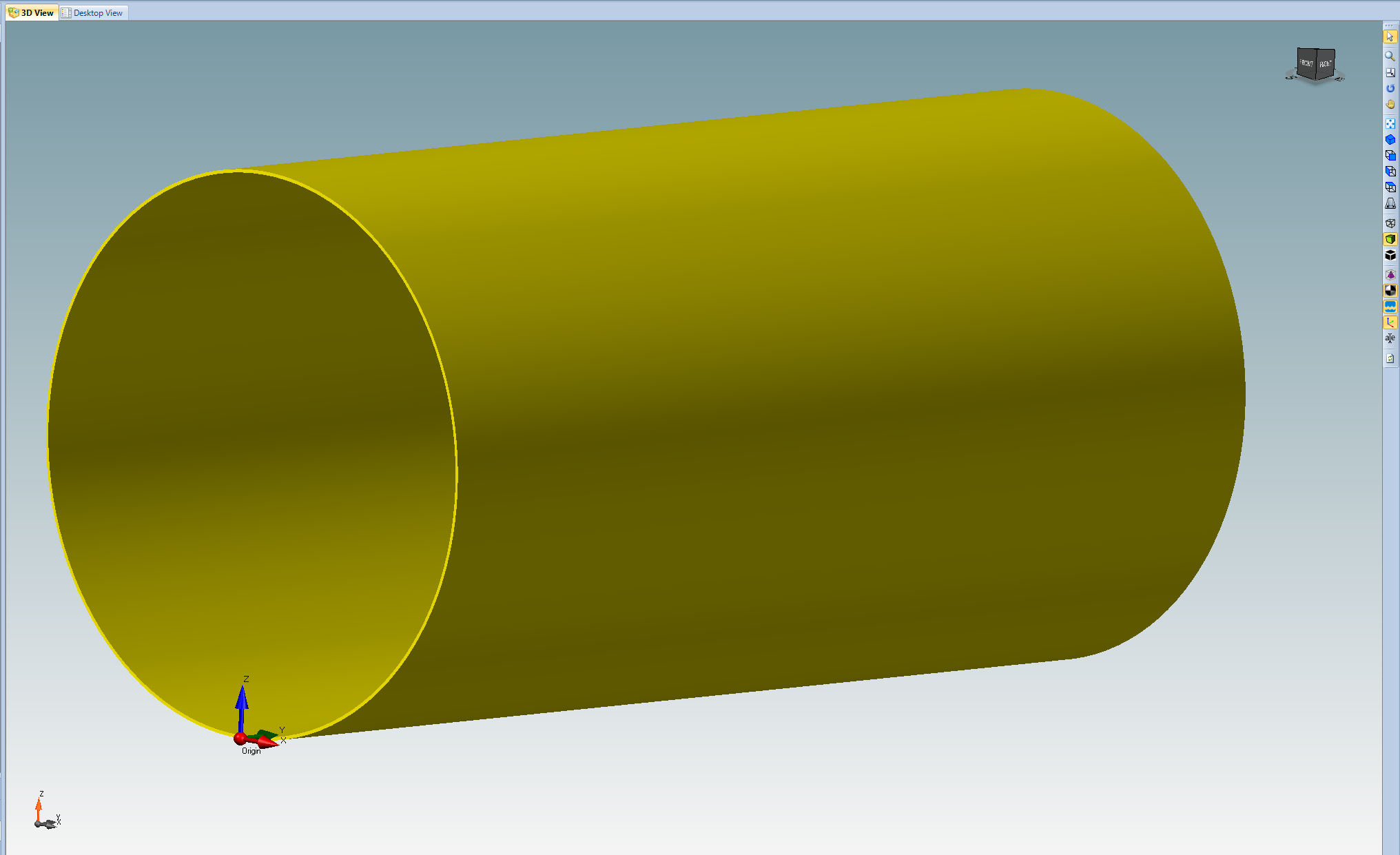
3D model of a cylinder
Buttons in the "Components" tab of the ribbon bar are enabled contextually, showing components that can be connected to the currently selected one.
Adding a head
It is now possible to proceed by adding a head to one side of the cylinder: from the "Components" tab of the ribbon bar, select the Torispherical Head icon. After clicking on it, NextGen asks at what side of cylinder this head should be connected to: click "OK" to confirm left side.
The component editing form for Torispherical Head will be shown: differently from the previous component, the "OK" button is already clickable and the semaphore shows a green light: this happens because NextGen infers some characteristics from the connected component. In this case, material and inside diameter are copied from the cylinder. No other value is needed, hence the validation occurs.
The user can click "OK" to add this head to the model or change some properties in order to have a better design: for instance, heads can be thinner than cylinders and joint efficiency can be unitary if they are built in a single piece.
Tip: joint efficiency set at Item level can lead to over conservative results on heads made from a single piece: it is a good practice to adopt a safe value at Item level as general efficiency, i.e. 0.85, then modify single components that can take advantage of unitary efficiency by acting on their own value under "Design conditions".
When the head is added to the model, it can be rapidly cloned on the opposite side by right-clicking on it and selecting "Copy":
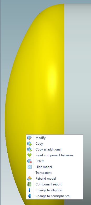
Copying a torispherical head
The head will then be copied to the other side of the cylinder.
From the same menu some actions contextual to the selected element can be choosen. For instance, it is possible to:
Insert an element between head and cylinder
Switch from one type of head to another
Create calculation report
These actions may be different from component to component.
After cloning the head, it is possible to proceed by adding a nozzle to the model.
Adding a nozzle
Select the main cylindrical shell, then from the "Components" tab of the ribbon bar select the "Nozzle" icon. The component editing window for Nozzle will be shown.
Set material to P265GH following the same procedure followed in shell material selection.
*Tip: besides browsing the whole database, it is possible to type in the material field the name of the desired material: a pop-up window will be displayed, allowing a faster material selection. Moreover, right-clicking on the same text input shows a list of recently used materials, speeding up things a little more.\
*
Under "Geometry", click on "Pipes database" button and proceed by selecting a 4" STD pipe. Dimensions and undertolerance will be read from database, saving time while designing. Set the nozzle height equal to 100 mm.
Under "General", enable the "Nozzle with a longitudinal weld" property. Some properties in NextGen have a contextual help icon:

"Nozzle with a longitudinal weld" property
By clicking on it, an explanation about the current property is shown; in this case, a clarification about how this property affects the calculations.
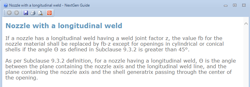
Contextual help for the "Nozzle with a longitudinal weld property"
Finally, under "Position", set the distance from the shell border. For simplicity, click on "Center" to position the nozzle at 500 mm. The input phase is now complete and the component can be validated; the validation will start automatically.
Before clicking "OK", take a look at the preliminary report:
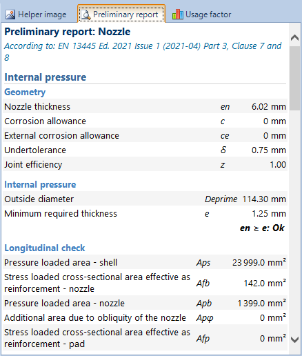
Preliminary report
Variables calculated by the software are shown here. Click "OK" to add the nozzle to your item.
Adding a flange
As a final component, add a standard flange on top of the nozzle just created: right-click on the nozzle, then select "Add standard flange" > "Welding neck" from the contextual menu:
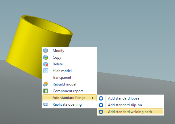
Adding a standard flange
In the following window, select the flange rating, e.g. 16.
The component editing window for this flange will open: set material to P280GH (tmin = 35 mm, tmax = 70 mm). The flange is now validated and the "OK" button is enabled. Notice that the bolts and gasket validation is disabled:

"Disable bolts and gasket validation" property
Since this flange is a peripheral standard flange, the validation for bolts and gasket can be omitted.
Adding more components
NextGen interface is designed to show a consistent interface across different components. Properties are listed in the clearest way possible and once familiar with simple components like shells, the user will be able to follow the design of a more complex component without much trouble.
Contextual help buttons are there to clarify any doubt regarding specific properties.
The definition of the vessel with more components can proceed linearly, following the same procedure for each component.
Setting a liquid level
A common operation in pressure vessels' design is the definition of an hydrostatic pressure in operating conditions. Using NextGen, this can be easily done by selecting a body component (for an horizontal vessel the cylindrical shell; for a vertical vessel, the component where liquid level lies), then clicking on the glass icon in the "Item" tab of the ribbon bar.
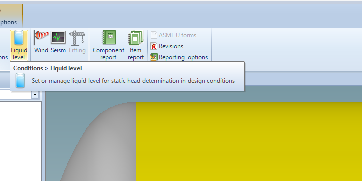
Setting a liquid level
Liquid name, height and density must then be set. The liquid level is relative to the lowest point of the current component.
After clicking "OK", the liquid level is rendered as a blue surface:
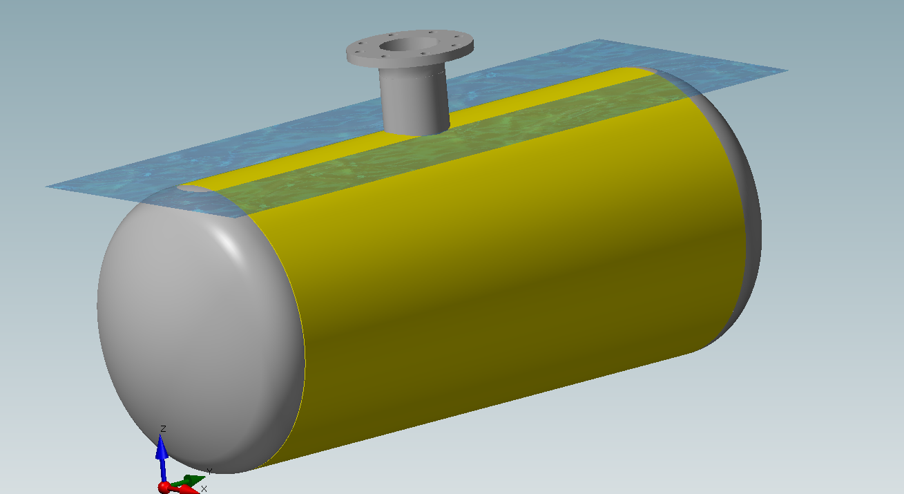
Liquid level on the 3D model
Some remarks:
In testing conditions, the liquid level is always automatically calculated filling the whole vessel with water.
In operating conditions, every component in contact with the liquid will have an hydrostatic pressure automatically calculated. The value is shown -- and can be overwritten -- in "General", "Overpressure due to static head".
Printing
A report for a single component or the whole item can be created any time.
The single component report is particularly helpful when the reason behind a calculation error must be understood: NextGen produces a complete report, with all calculations done by the software, printing every formula used and therefore allowing a manual verification of the calculations.
To produce a complete item report, click on the pile of books icon in the "Item" tab of the ribbon bar:
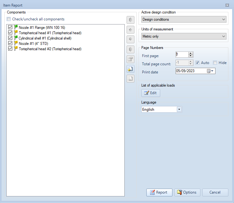
"Item report" window
In the following window it is possible to include, exclude or reorder components, or customize the printing options. For advanced options click on the "Options" button in the bottom of the window. You can find more information on the available report options in this article. Once the report is set-up, click on "Report" to start its creation.
The calculation report is easily browsable via integrated viewer or exported in both .PDF and Word .DOCX formats.
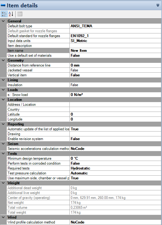
Main item properties
Item properties are always available by selecting "File" > "Item properties". Here are some of the most important options.
Please note that some sections may not be visible: use the arrows to jump through tabs.

Categories present in the "Item properties" window
General
In this section some default values can be choosen, like flange reference standard, default bolt type or default set of materials. In the case of calculations according to ASME, reference publication -- metric or customary -- and input units system can be set here.
Geometry
You can set a vertical item orientation in this section.
Test
Under "Test" it is possible to choose between different test configurations (none, hydrostatic test, pneumatic test or both hydrostatic and pneumatic test), set a manual test pressure and specify test condition options. For ASME VIII Division 1 a complete hydrostatic test can be set here: internal pressure calculation will be repeated using test pressure and an allowable value based on the yield strength of the material.
Location, seism, wind
These options allows to set geographical position of the item and options pertinent to seism and wind according to codes like ASCE, Eurocode, UBC, NTC.
Reporting
In this section, information printed on the upper-right corner of the report can be set.
Fatigue
For EN13445, ASME VIII Div 1 and ASME VIII Div 2, this section allows the definition of a fatigue analysis on the current vessel (fatigue screening for ASME codes).
Main program options
From "Tools" > "Options" it is possible to set different program options. Here's a recap:
General options
Under "General" it is possible to set working directories for the software, especially useful in a network environment where files and custom database must be shared between different users.
Communications
If a proxy is needed to access the internet, it can be set from here.
Reporting
Default reporting options can be set here. Each item can use these options or override them with a different, per-item specific set. Options include which summary pages must be printed and other options can be set by selecting a different sub-section from tabs placed on the left: validation warnings can be excluded from here, output units changed and report header plus logo set.
Components
Under "Components" a checkbox labeled "Enable geometric relationships between components" can be found: NextGen takes care of relative components resizing, keeping their dimensions syncronized. When this behaviour is unwanted, it is possible to use this option.
A detailed explanation of this function is available in this article:
In the same section, an option to define different pressures between adjacent components is available: check this if you want to modify the pressure value from within a component editing window.
Ask for help
NextGen has an integrated help request form, called "Ask for support": this form can be opened by clicking on the "Ask for support" button in the "Help" tab of the ribbon bar.
A detailed explanation of this function is available in this article.
Additional resources
Tecnical articles section on Sant'Ambrogio website is constantly updated. Here's a list of useful resources; full list of support articles is available at the following link:
https://nextgen.sant-ambrogio.it/en/categories/knowledge-base
Visit this article for a guide on using the Heat Exchanger Wizard
Visit this article for a guide on how to validate an attachment according to WRC 107, WRC 537 or WRC 297 bulletins
Visit this article for a guide on how to create additional components (design mode similar to Sant'Ambrogio Classic Edition software)